![]()
Construction guidelines for tree trenches and tree boxes

Standard keys to success in bioretention construction apply to trees for bioretention, including the following.
- Plan for feasible temporary and permanent erosion and sediment control techniques and sequencing.
- Plan for temporary and permanent erosion and sediment control techniques, sequencing, and pay items, and prepare a thorough SWPPP plan. Example techniques include compost logs (MnDOT 2573) and plastic sheeting (MnDOT 2575), and diversion berms (MnDOT 2573).
- Plan to minimize or avoid soil compaction to the extent feasible. Techniques include, for example, using drivable mats, using tracked machinery, and machinery with long arms to avoid having to drive in tree trenches.
- Designate a stormwater supervisor to make sure someone is responsible for erosion and sediment control.
- Plan for snow storage during (if applicable) and after construction
- Construction administration and communication with contractor
- Effective communication during pre-construction meeting.
- Include “check points” in specifications with timelines – points of inspection which must be approved before proceeding to next step of construction. These will vary depending on specific project,but will include, for example, approval of required submittals, and required testing, such as, for example infiltration tests.
- Ensure checkpoints are approved prior to proceeding to next steps. Where applicable, require signature by Contractor, Designer, and Chief Inspector prior to proceeding to next step.
- Require submittals for material to be used, including, sources and certifications where applicable.
- Specify required tests and tolerances.
See the bioretention section for other construction guidelines and specifications.
Contents
Construction guidelines and specifications specifically for trees for bioretention
In addition to general bioretention guidelines and specifications, the following guidelines and specifications apply specifically to trees for stormwater design.
- Tree material and installation guidelines
- Tree soil quality and volume guidelines
- Tree opening guidelines
- Tree openings need to be large enough to allow for trunk flare. Minimum recommended tree opening dimension is 5 feet by 5 feet.
- The use of tree grates is discouraged in order to protect the tree root flare.
- Tree openings need to be protected from foot and vehicular traffic.
- Tree spacing guidelines
- For street trees, a minimum spacing of 30 feet on center is recommended for large trees to allow their canopies to grow to their full size. This also makes it easier to provide adequate soil volumes for each tree.
- Guidelines for providing rootable soil volume for tree root growth and bioretention under pavement. Where there is not enough open space for traditional bioretention, several techniques exist to protect soil volume under pavement from traffic compaction so that this soil can be used both for bioretention and tree root growth. Examples of these techniques include:
- Structural cells
- Rock based structural soil
- Sand based structural soil
- Soil boxes
Each of the above techniques is described and compared below. Links to construction guidelines are also provided.
Suspended pavement

In areas that do not have enough open space to grow large trees, techniques like suspended pavement can be used to extend tree rooting volume under HS-20 load bearing surfaces and create favorable conditions to grow large trees in urban areas. This rooting volume can also be used for bioretention. While suspended pavement has been built in several different ways, all suspended pavement is held slightly above the soil by a structure that “suspends” the pavement above the soil so that the soil is protected from the weight of the pavement and the compaction generated from its traffic.
One of the earliest examples of trees grown in suspended pavement is in Charlotte, North Carolina, where a reinforced concrete sidewalk was installed over the top of poured in place concrete columns. While this is an effective way to grow large trees, it is labor intensive and requires intensive surveying to ensure that column heights are precise.
A more recently developed, and less labor intensive, technique to build suspended pavement is through the use of soil cells. An example is Silva Cells, modular proprietary pre-engineered structural cells manufactured by Deeproot Green Infrastructure. Other examples are RootSpace systems manufactured by GreenBlue Urban and Stratavault systems manufactured by Citygreen. The modular design allows flexibility to size the rooting/bioretention volume as needed for each site. Underground utilities can be accommodated within these systems. Because soil in a suspended pavement system is protected from compaction from loads on pavement above the cells, a wide range of soils can be used in these systems, so soil can be tailored to desired functions (e.g. tree growth and stormwater management). Construction documents and specifications for a wide range of soil cell applications can be found on the manufacturers' websites (Deeproot Green Infrastructure, GreenBlue Urban, and Citygreen).
Photo galleries below illustrate the Silva Cell, RootSpace, and Stratacell/Stratavault technologies.
- Images for Silva Cell technology. Source: Kestrel Design Group, Inc. Click on an image for enlarged view.
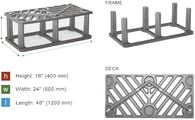
Silva cells.
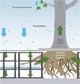
Schematic drawing of Silva cell suspended pavement system using soil cells and pervious pavement used for bioretention.
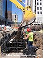
Installation of Silva cell system at Marquette Avenue project, Minneapolis, MN.
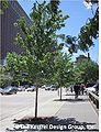
Completed Silva cell system at Marquette Avenue project, Minneapolis, MN.


- Images for RootSpace technology. Source: GreenBlue Urban. Click on an image for enlarged view.
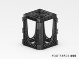
RootSpace.
Schematic of RootSpace system.
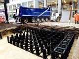
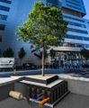
Installation of RootSpace system at RSM Plaza, Minneapolis, MN.
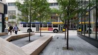
Completed RootSpace system at RSM Plaza, Minneapolis, MN.


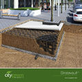
- Images for Stratacell/Stratavault technology. Source: Citygreen. Click on an image for enlarged view.
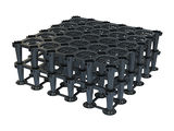
Stratavault
Schematic of Stratavault system.
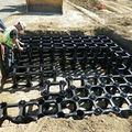
Installation of a Stratavault system.
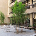
Completed Stratacell system at Pace University, New York.


Rock-based structural soils


Rock based structural soils are engineered to be able to be compacted to 95 percent Proctor density [1] without impeding root growth. Rock based structural soils are typically gap graded engineered soils with
- stones to provide load bearing capacity and protect soil in its void spaces from compaction,
- soil in rock void spaces for tree root growth, and
- tackifier to keep the soil uniformly distributed in the rock void spaces (tackifier is only found in some kinds of rock based structural soil).
Stone lattice
Desired characteristics for the stone base used in rock based structural soils include the following.
- The stones should be uniformly graded and crushed or angular for maximum porosity, compaction, and structural interface (Bassuk et al 2005).
- Mean pore size should be large enough to accommodate root growth (Lindsey 1994).
- Significant crushing of stone should not occur during compaction (Lindsey 1994).
According to University of California-Davis (1994), 2 inch stones would be able to support most tree roots. Because limestone has been found to crush on some projects, granite stone is recommended. If limestone is used, it should meet specifications described in the permeable pavement section of this manual.
Soil
Soil needs to have adequate nutrient and water holding capacity to provide for the tree’s needs.
Tackifier
The tackifier, if used, should be non-toxic and non-phototoxic.
Construction drawings are available on Cornell University’s website, including
- detail and plan for using structural soil in a planting island;
- detail and plan for using structural soil in a limited soil volume planter;
- detail for using structural soil with permeable pavers; and
- detail for structural soil breakout zone.
Types of structural soils
Several types of rock based structural soils have been developed, including
- Cornell University (CU) structural soil: 80 percent stone with size ranging from 0.75 to 1.5 inches and 20 percent loam to clay loam soil with minimum 5 percent organic matter, by dry weight, and hydrogel to uniformly mix the stone and soil (Bassuk et al., 2005). Patented formula available only from licensed producers to ensure quality control. Considerable information can be found on Cornell University's website.
- Stalite structural soil: 80 percent Stalite, a porous expanded slate rock (0.75 inches), and 20 percent sandy clay loam soil (by volume)(Xiao and McPherson 2008).
- Swedish structural soil
- University of California (UC) Davis structural soil
Note: University of California (UC) Davis structural soil is not designed to be load-bearing and therefore should not be compacted. This structural soil is 75 percent lava rock (0.75 inches) and 25 percent loam soil (by volume) (Xiao and McPherson, 2008). Because of the lava rock, this soil stores more stormwater than other structural soils and has a very high surface area to facilitate pollutant trapping.
Wenz provides a discussion of some structural soils, including case studies.
Design considerations for trees growing in structural soil
Day and Dickinson (2008) provide information on use of trees in structural soils, including design specifications. The following considerations should be made in using structural soils.
- Soil pH: Care must be taken to select species tolerant of structural soil pH. For example, if limestone based structural soil is used, trees tolerant of alkaline pH must be selected, as limestone can raise the pH of soil to 8.0 or higher (Bassuk, 2010 soil debate; Urban, 2008).
- Drainage Rate: Because rock based structural soils drain quickly (greater than 24 inches per hour), designers should select tree species tolerant of extremely well drained soils (Bassuk, 2010).
- Volume of rock based structural soil needed for healthy tree growth: Because only 20 percent of the volume of a rock based structural soil is actually soil, a greater total volume of rock based structural soil is needed compared to growing the same size tree in a sandy loam soil. A study by Grabowsky et al., (2009) found the water holding capacity of a CU structural soil was about half that of a typical soil, meaning about 2 parts of structural soil are needed to provide the soil value of 1 part of loam soil. This could be reduced to a ratio of 1.5:1 if soil is planted around the root ball. Similarly, an on-going study at Bartlett Tree labs is finding that over the past 9 years, trees growing in loam soil in suspended pavement have been consistently outgrowing trees growing in equal volumes of rock based structural soils, stalite soil, and compacted soil.
Based on the above studies, Urban (2008) recommends: “Given the extreme inefficiency of the ratio of excavated volume to soil usable by the tree, strips of structural soil less than 20 feet wide might be better constructed as soil trenches or structural cells, where more soil can be included for less cost. A 5-foot wide soil trench set of structural cells…will provide more soil usable by the tree than a 20 foot wide trench of soil/aggregate structural soil. Soil/aggregate structural soils may have applications as a transition to other options, and to add soil in places where other options may not be practical. These might include tight, contorted spaces and fills around utility lines and against foundations where full compaction is required.”
More information about rock based structural soils is available online at
- Cornell University’s website; and
- a joint website by Cornell University’s, Virginia Tech, Rutgers University, and University of California Davis.
Sand based structural soil
Sand based structural soils were first developed in Amsterdam when some trees were in poor condition because of an “unfavorable rooting environment” (Couenberg, 1993). Because the natural soils in Amsterdam, bog-peat, was non-load bearing, the top 2 meters of soil had been replaced with a medium coarse sand, which had insufficient nutritional value. Amsterdam soils were developed in an effort to grow better trees but still provide adequate bearing capacity for pavement bearing light loads, such as sidewalks. The Dutch studied various mixes for tree growth, soil settlement, and several other parameters. The resulting Amsterdam Tree Soil contains medium coarse sand with 4 to 5 percent organic matter and 2 to 4 percent clay by weight and also meets other criteria, including, for example, (1) the medium coarse sand must meet specific gradation requirements, (2) soil mix must be free of salt, (3) mix must contain less than 2 percent particles below 2 micrometers, and (4) amount of particles below 2 micrometers must be considerably less than the amount of organic materials (Couenberg 1993).
All medium coarse sand (the layer above the Amsterdam Tree Soil) is compacted to 95 percent to 100 percent Proctor density. Amsterdam tree soil is not compacted to 100 percent density, but “is compacted until the soil has a penetration resistance between 1.5 and 2 MegaPascal (187 to 250 pounds per square inch (PSI)) ... Comparison of soil density values after filling with soil density at 100 percent Proctor Density has shown that soil density of Amsterdam Tree Soil after filling amounts to 70 to 80 percent Proctor Density” (Couenberg 1993).
Amsterdam Tree Soil was found to settle 19 millimeters [0.75 inches] in 3 years compared to the surrounding pavement, which was acceptable according to Dutch standards (Couenberg 1993), but may not be acceptable to many communities in the US to minimize risk of litigation related to trip and fall hazards.
The standard design in Amsterdam includes the following from bottom to top.
- Ground water table 1 to 1.2 meters below ground level
- Saturation zone 10 to 20 centimeters
- Layer of compacted, non-saturated sand
- Amsterdam tree soil compacted in 2 layers of 40 to 50 centimeters
- Compacted layer of 10 centimeters medium coarse sand for paving.
- Pavement, typically concrete pavers 30 x 30 x 5 centimeters (Couenberg 1993)
While Amsterdam sand based soils work well in Amsterdam, trees grown in Amsterdam soils in Minnesota would likely need significant irrigation, as they have low water holding capacity. Amsterdam receives an average of 36 inches of rain per year, which is higher than the range of average yearly rainfall in Minnesota. Rainfall events are also more frequent and lower intensity in Amsterdam than in Minnesota. Summer temperatures are also higher in Minnesota than in Amsterdam, resulting in higher water needs by trees. According to Couenberg (1993), who helped develop Amsterdam soils, “the Amsterdam tree soil has been developed in an area where there is sufficient rainfall. If this soil is used in other climatic areas, adaptations to the tree pit will have to be made after the local situation has been monitored.”
Most of Amsterdam also has a high water table which is controlled to have almost no seasonal fluctuation, and groundwater wicks up into tree rooting zones by capillary action, so trees always have access to water from the ground water table. According to Urban (2008), “tests of Amsterdam planting soil in other locations in Europe without high water tables showed less promising results with overly dry soil, which required significant supplemental water.” So, in summary, sand based structural soils may be a viable in Minnesota if some settlement is acceptable with light structural loads and trees are irrigated.
For more information on Amsterdam Tree Sand see [2]
Soil boxes
Soil boxes are concrete boxes designed for bioretention. They are typically proprietary products, such as, for example, the boxes made by Filterra and Contech. Rooting volume capacity of these boxes is typically limited to large shrubs. Soil volumes provided by these boxes are typically not sufficient to grow healthy large trees. A standard 6 feet by 6 feet Filterra box, for example, provides 72 cubic feet of soil, assuming a 2 foot depth of soil. Given that the recommended soil volume for trees is 2 cubic feet of soil per 1 square foot of tree canopy, this is only enough to support a tree with a 5 foot radius canopy.
Comparison of soil volumes, open space, and underground space needed for open grown tree vs. tree in suspended pavement, rock based structural soil, sand based structural soil, and soil boxes.
Link to this table
| Technique | Soil volume provided per cubic foot rooting zone (not including pavement profile where applicable) | Open space needed to grow a 30’ diameter canopy tree assuming 34” soil depth1 | Total volume recommended per 30’ diameter canopy tree1 | Structural Capacity (Traffic load supported) |
|---|---|---|---|---|
| Open tree pit (no pavement or foot traffic above rooting space) | 1 ft3 | 500 2 | 1413 ft3 | Not even foot traffic should be allowed on open tree pits |
| Structural cells | 0.92 ft3 | 5 ft by 5 ft | 1536 ft3 | Can support vehicle loading up to AASHTO H-20 rating of 32,000 lbs. per axle (U.S. Federal Highway Bridge Standard). This rating refers to the ability of a roadway to safely accommodate 3-4 axle vehicles, such as a large semi-truck and trailer (Deeproot website) |
| Rock based structural soils3 | 0.5 to 0.75 ft2 | 5 ft by 5 ft | 2826 to 2120 ft3 | Can be used under pedestrian mall paving, sidewalks, parking lots, and low-use access roads |
| Sand based structural soils | 1 ft3 | 5 ft by 5 ft | 1413 ft3 | No standard test data available; Amsterdam sand settled 19 mm in 3 years compared to the surrounding pavement (Couenberg 1993), which is generally not acceptable in the U.S. |
| Soil boxes | 1 ft3 | Not large enough to grow 30 ft diameter tree | Not large enough to grow 30 ft diameter tree |
1 Based on 2 ft3 of soil volume per 1 ft3 of canopy area, assumes Silva Cells are used for structural cells, assumes 92% void space in Silva Cells; assumes CU Structural Soil is used for rock based structural soil; assumes soil component of rock based structural soil is 20%.
2 Although a typical rock-based soil includes 80% rock and 20% soil, the effective volume of the soil is greater than 20%. The recommended ratios in the table reflect information provided in Grabowsky et al., 2009, and by Dr. Nina Bassuk, Cornell University (personal communication).
Minnesota Department of Transportation example construction protocols
Preliminary analysis and selection
Recommended number of soil borings, pits or permeameter tests for bioretention design. Designers select one of these methods.
Link to this table
| Surface area of stormwater control measure (BMP)(ft2) | Borings | Pits | Permeameter tests |
|---|---|---|---|
| < 1000 | 1 | 1 | 5 |
| 1000 to 5000 | 2 | 2 | 10 |
| 5000 to 10000 | 3 | 3 | 15 |
| >10000 | 41 | 41 | 202 |
1an additional soil boring or pit should be completed for each additional 2,500 ft2 above 12,500 ft2
2an additional five permeameter tests should be completed for each additional 5,000 ft2 above 15,000 ft2
Field verification testing prior to pond construction
- Soil hydraulic group represent what is stated in SWPPP (Stormwater Pollution Prevention Plan)
- Seasonally high water table not discovered within 3 feet of the excavated pond base within a test pit
- Commonly will test bottom of proposed pond for soil compaction (subsequent subsoil ripping) prior to media placement
- Commonly will test bottom of proposed pond for insitu infiltration rate by test pit or water filled barrel placed on pond base surface
Filter media and material testing
- Existing soil (option 1 below) or Washed sand (option 2 below), and compost certification
- Washed course aggregate choker certification
- Other treatment material certification of iron filings, activated charcoal, pH buffers, minerals, etc.
- Geotextile separation fabric certification
- Drain-tile certification (if filtration is specified)
- Seed source certification
- Barrel test verification of infiltration rate using 2.5 feet of imported 3877 Type G media
Field verification testing/inspection/verification during construction
- Water drains away in 48 hours
- Infiltration drainage rate does not exceed 8.3 inches per hour
- No tracking/equipment in pond bottom
- No sediment deposits from ongoing construction activity, media perimeter controls kept functional
- Forebay is trapping settleable solids, floating materials, and oil/grease
- Area staked off
Notice of Termination (NOT) verification
- Option 1. Amending existing HSG soils with compost or other treatment material. Test the infiltration rate of each infiltration basin using a double ring infiltrometer prior to completion of the basin. Conduct the test at the finished grade of the basin bottom, prior to blending the compost with the in-situ soils or sand. Ensure infiltration rates meet or exceed greater of two times the designed infiltration rate or 2 inches per hour. Conduct a minimum of five tests per representative acre of basin area and a minimum of five tests per basin. Conduct double ring infiltrometer tests in accordance with ASTM standards. Thoroughly wet test areas prior to conducting infiltrometer tests.
- Option 2. Importing 3877 Type G Filter Topsoil Borrow (may be amended with other treatment material). Ensure infiltration rates meet or exceed greater of two times the designed infiltration rate or 2 inches per hour, or rate specified in the plan. Conduct a minimum of five tests per representative acre of basin area and a minimum of five tests per basin. Conduct double ring infiltrometer tests in accordance with ASTM standards. Thoroughly wet test areas prior to conducting infiltrometer tests. Amend soils with additional washed sand if rates less than specified in the contract, or compost if rates exceed 8.3 inches per hour.
The permanent stormwater management system must meet all requirements in sections 15, 16, and 17 of the CSW permit and must operate as designed. Temporary or permanent sedimentation basins that are to be used as permanent water quality management basins have been cleaned of any accumulated sediment. All sediment has been removed from conveyance systems and ditches are stabilized with permanent cover.
References
- Bassuk, Nina. 2010. Using CU-Structural Soil to Grow Trees Surrounded by Pavement. In The Great Soil Debate Part II: Structural soils under pavement. ASLA Annual Meeting Handout.
- Bassuk, Nina, Jason Grabosky, and Peter Trowbridge. 2005. Using CU-Structural Soil™ in the Urban Environment.
- Couenberg Els. A.M. 1993. Amsterdam Tree Soil. In: The Landscape Below Ground. Proceedings of an international workshop on tree root development in urban soils.
- Day, S.D, and S.B. Dickinson (Eds.) 2008. Managing Stormwater for Urban Sustainability using Trees and Structural Soils. Virginia Polytechnic Institute and State University, Blacksburg, VA.
- Grabosky, Jason, Edward Haffner, and Nina Bassuk. 2009. Plant Available Moisture in Stone-soil Media for Use Under Pavement While Allowing Urban Tree Root Growth. Arboriculture& Urban Forestry 35(5): 271-278.
- Lenth, John and Rebecca Dugopolski (Herrera Environmental Consultants), Marcus Quigley, Aaron Poresky, and Marc Leisenring (Geosyntec Consultants). 2010. Filterra® Bioretention Systems: Technical Basis for High Flow Rate Treatment and Evaluation of Stormwater Quality Performance. Prepared for Americast, Inc.
- Lindsey, Patricia, Ed. 1994. The Design of Structural Soil Mixes forTrees in Urban Areas – Part II. Growing Points 1(2). University of California.
- Urban, J. 2008. Up by Roots. International Society of Arboriculture. 479 pages.
- Wenz, E. 2012. Structural Soil for Trees and Stormwater Management. Presented at 2012 Clean Water Summit. University of Minnesota Landscape Arboretum. September 13, 2012.
- Xiao, Qingfu and E. Greg McPherson. 2008. Urban Runoff Pollutants Removal Of Three Engineered Soils. USDA Center for Urban Forest Research and UC Davis Land, Air and Water Resources.
Related pages
- Overview for trees
- Types of tree BMPs
- Plant lists for trees
- Street sweeping for trees
- References for trees
- Supporting material for trees
The following pages address incorporation of trees into stormwater management under paved surfaces
- Design guidelines for tree quality and planting - tree trenches and tree boxes
- Design guidelines for soil characteristics - tree trenches and tree boxes
- Construction guidelines for tree trenches and tree boxes
- Protection of existing trees on construction sites
- Operation and maintenance of tree trenches and tree boxes
- Assessing the performance of tree trenches and tree boxes
- Calculating credits for tree trenches and tree boxes
- Case studies for tree trenches and tree boxes
- Soil amendments to enhance phosphorus sorption
- Fact sheet for tree trenches and tree boxes
- Requirements, recommendations and information for using trees as a BMP in the MIDS calculator
- Requirements, recommendations and information for using trees with an underdrain as a BMP in the MIDS calculator
This page was last edited on 9 February 2023, at 16:11.