Guidance on calculating volumes for underground infiltration BMPs in the MIDS calculator
The Minimal Impact Design Standards calculator requires a user to input a value for water stored in an underground infiltration practice below the outflow (overflow) pipe and above the top of the underlying soil or engineered media. This is not a straightforward calculation because there are a wide variety of underground pipe shapes and because two different calculations must be made - one for storage in the pipe and another for storage in the media surrounding the pipe. If engineered media is used in the practice, the calculator also requires a calculation of the surface area of the engineered media. This calculation is fairly simple. Both these calculations can be made using a spreadsheet developed for this purpose.
Link to the spreadsheet: File:Underground storage volumes 3.xlsx
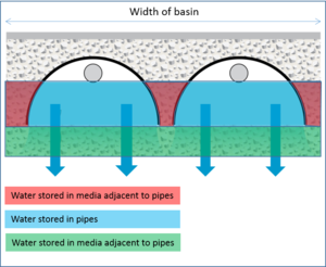
Water storage in an underground system is shown in the schematic to the right. As the schematic shows, water is stored within the pipes, in the media adjacent to the pipes, and in some designs, in media below the pipes. The water drains vertically into the underlying native soil. Outflows within each pipe control the amount of water that drains. Water stored above the outflows is returned to the storm sewer system.
Contents
Calculating underground pipe storage volume (VP)
To calculate underground pipe storage volume VP we need to add the volume stored in the pipes and in the media adjacent to and beneath the pipes.
Circular pipes
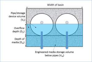
Considering a full circle pipe, shown in the schematic to the right, the volume of water stored in the open space within the pipes (Vpipes) is given by
\( ((r^2 * arccos((r - D_O)/(r))) - ((r - D_O) * sqrt((2 * r * D_O) - (D_O * D_O)))) * L_p * N_p \)
where
- r is the radius of the pipes (ft);
- DO is the overflow depth (ft);
- Lp is the length of the pipes (ft); and
- Np is the number of pipes.
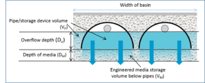
For a half-pipe configuration, the above equation can be used, but 1/2 the volume of the pipe must be subtracted. This is represented by the last term in the following equation\[ (((r^2 * arccos((r - D_O)/(r))) - ((r - D_O) * sqrt((2 * r * D_O) - (D_O * D_O)))) * L_p * N_p) - (π r^2 * L_p * N_p) \]
The above equations represent the volume below the bottom of the overflow. Water above the overflow is assumed to discharge through the overflow and not vertically below the outflow.
The total volume of pipe and media (Vt) that can hold water is given by
\( (D_O + D_M) * L_B * W_B \)
where
- DM is the depth of media below the pipes (ft);
- LB is the length of the underground basin (ft); and
- WB is the width of the underground basin (ft).
The volume of the media (VM) equals the difference between the total volume and the volume in the pipes (Vt - Vpipes), in cubic feet. The volume of water stored in the media is equal to VM times the porosity. The Excel spreadsheet calculates the amount of water stored in media below the pipes and in media adjacent to the pipes, but this differentiation is not needed if the porosity of all media is the same.
Rectangular or other flat-side pipes
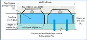
Considering the schematic to the right, the volume of water stored in the open space within the pipes (Vpipes) is given by
\( ((W_p * D_O *L_p) - ((D_O - H_1) * (W_p - W_O) * L_p) * N_p \)
where
- Wp is the width of the pipe at its base (ft);
- DO is the overflow depth (ft);
- Lp is the length of the pipes (ft);
- H1 is the height of the pipe at its first turn;
- WO is the width of the pipe at the bottom of the outlet (ft); and
- Np is the number of pipes.
The first set of terms computes the total volume, while the second set of terms accounts for pipes that are not rectangular. If the pipe is rectangular, the height at the first turn should be set equal to the overflow depth or the result will be incorrect.
The total volume of pipe and media (Vt) that can hold water is given by
\( (D_O + D_M) * L_B * W_B \)
where
- DM is the depth of media below the pipes (ft);
- LB is the length of the underground basin (ft); and
- WB is the width of the underground basin (ft).
The volume of the media (VM) equals the difference between the total volume and the volume in the pipes (Vt - Vpipes, in cubic feet. The volume of water stored in the media is equal to VM times the porosity. The Excel spreadsheet calculates the amount of water stored in media below the pipes and in media adjacent to the pipes, but this differentiation is not needed if the porosity of all media is the same.
The above calculations are limited to pipes with a single turn. However, as illustrated in the example below, the difference in volume between a rectangular pipe system and a system employing other flat-sided shapes is likely to be insignificant.
Other methods for calculating volumes
The volumes needed for entry into the MIDS calculator can be calculated in other ways, or they may be included in the manufacturer specifications.
Example applications of the Excel spreadsheet
The following examples utilized the Excel spreadsheet to generate inputs for the MIDS calculator.
Link to Excel spreadsheet: File:Underground storage volumes 3.xlsx
Example for half circle pipes
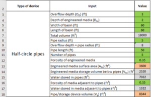
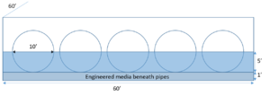
Assume an underground infiltration systems consists of 5 half-circle pipes, 50 feet in length and 10 feet in diameter. The pipes rest on an engineered media layer that is 2 feet thick. The bottoms of the outflow pipes are located 3 feet above the surface of the engineered media. The pipes sit in a basin that is 60 feet wide and 60 feet long. The porosity of the media is 0.35 cubic centimeters per cubic centimeter. The screen shot to the left shows the schematic for this example. The top image to the right illustrates the Excel spreadsheet used to make the calculations. The lower screen shot illustrates where the Excel calculations should be entered into the MIDS calculator.
Ensure the other values used in the Excel spreadsheet match the values input into the calculator. Note that the pipe storage volume, Vp, includes water stored in pipes and water stored in media adjacent to the pipes but above the engineered media below the pipes. In this example, the bulk of water is stored in the pipes. In this example, there may be up to 2 feet of additional water collected above the outflow pipe. This water must leave the underground system within 48 hours, presumably through the outflow. See the section on bounce for more information.
Note the MIDS calculator uses a single value for media porosity. This is for the media below the pipes. The Excel spreadsheet allows the user to specify different media porosities adjacent to and below the pipes. The Excel spreadsheet does not calculate water stored in media beneath the pipes but provides the media surface area, which is needed to calculate water storage in the media.
Example for full circle pipes
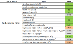
Assume an underground infiltration systems consists of 5 full-circle pipes, 50 feet in length and 10 feet in diameter. The pipes rest on an engineered media layer that is 1 feet thick. The bottoms of the outflow pipes are located 5 feet above the surface of the engineered media. The pipes sit in a basin that is 60 feet wide and 60 feet long. The porosity of the media is 0.35 cubic centimeters per cubic centimeter. The screen shot to the left shows the schematic for this example. The top image to the right illustrates the Excel spreadsheet used to make the calculations. The lower screen shot illustrates where the Excel calculations should be entered into the MIDS calculator.
Ensure the other values used in the Excel spreadsheet match the values input into the calculator. Note that the pipe storage volume, Vp, includes water stored in pipes and water stored in media adjacent to the pipes but above the engineered media below the pipes. In this example, the bulk of water is stored in the pipes. In this example, there may be up to 5 feet of additional water collected above the outflow pipe. This water must leave the underground system within 48 hours, presumably through the outflow. See the section on bounce for more information. The MIDS calculator will not allow storage of water beyond a depth of 6.52 feet for an A soil with an infiltration rate of 1.63 inches per hour. This is because of the 48 hour drawdown requirement. For an A soil with an infiltration rate of 0.8 inches per hour, the depth limitation is 3.2 feet. This includes both water stored in the pipes and in the media beneath the pipes.
Note the MIDS calculator uses a single value for media porosity. This is for the media below the pipes. The Excel spreadsheet allows the user to specify different media porosities adjacent to and below the pipes. The Excel spreadsheet does not calculate water stored in media beneath the pipes but provides the media surface area, which is needed to calculate water storage in the media.
Example for rectangular pipes
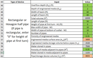
Assume an underground infiltration systems consists of 5 rectangular pipes, 50 feet in length and 10 feet wide at the base. The pipes rest on an engineered media layer that is 2 feet thick. The bottoms of the outflow pipes are located 3 feet above the surface of the engineered media. The pipes sit in a basin that is 60 feet wide and 60 feet long. The porosity of the media is 0.35 cubic centimeters per cubic centimeter. The screen shot to the left shows the schematic for this example. The top image to the right illustrates the Excel spreadsheet used to make the calculations. The lower screen shot illustrates where the Excel calculations should be entered into the MIDS calculator.
Ensure the other values used in the Excel spreadsheet match the values input into the calculator. Note that the pipe storage volume, Vp, includes water stored in pipes and water stored in media adjacent to the pipes but above the engineered media below the pipes. In this example, the bulk of water is stored in the pipes. In this example, there may be up to 2 feet of additional water collected above the outflow pipe. This water must leave the underground system within 48 hours, presumably through the outflow. See the section on bounce for more information.
Note that the MIDS calculator uses a single value for media porosity. This is for the media below the pipes. The Excel spreadsheet allows the user to specify different media porosities adjacent to and below the pipes. The Excel spreadsheet does not calculate water stored in media beneath the pipes but provides the media surface area, which is needed to calculate water storage in the media.
For the example of rectangular pipes, having the pipes five-sided instead of rectangular would slightly decrease the storage volume. For example, having a turn in the pipe at a height of 2 feet would decrease the overall volume retention by about 100 cubic feet out of a total retention of more than 8500 cubic feet. Thus, in most underground storage systems, assuming a rectangular system does not introduce significant error into the calculations.
This page was last edited on 23 November 2022, at 19:11.
