![]()
Requirements, recommendations and information for using stormwater pond as a BMP in the MIDS calculator


A constructed stormwater pond is a non-volume reducing BMP. While this BMP does not provide stormwater volume reduction toward the performance goal or on an annual basis, it does provide annual pollutant load reductions. Annual pollutant reductions are applied in three levels based on pond design.
Contents
Changes to Version 4 of the MIDS Calculator
- The USER must enter a bypass percent for this BMP. See the guidance for determining bypass percent.
- Users can specify a constructed stormwater pond with an iron-enhanced filtration bench to allow dissolved phosphorus removal. To achieve this, the user is asked whether amendments have been incorporated into the pond design. The user answers yes or no. If the user answers "No", there is no removal of dissolved phosphorus. If the user answers "Yes", phosphorus removal is 40 percent of the influent dissolved phosphorus. This removal value is not affected by the pond design level.
- The particulate phosphorus credit has been reduced from 62 to 60 percent for Design Level 1 ponds to match the TSS reduction. Particulate pollutant removal cannot exceed sediment removal.
MIDS calculator user inputs for constructed stormwater pond
For constructed stormwater pond BMP, the user must input the following parameters to calculate the pollutant load reductions associated with the BMP.
- Watershed tab
- BMP Name: this cell is auto-filled but can be changed by the user.
- Routing/downstream BMP: if this BMP is part of a treatment train and water is being routed from this BMP to another BMP, the user selects the name of the BMP from the dropdown box to which water is being routed. All water must be routed to a single downstream BMP. Note that the user must include the BMP receiving the routed water in the Schematic or the BMP will not appear in the dropdown box.
- BMP Watershed Area: BMP watershed areas are the areas draining directly to the BMP. Values can be added for four soil types (Hydrologic Soil Groups (HSG) A, B, C, D) and for three Land Cover types (Forest/Open Space, Managed Turf and impervious). The surface area of the BMP should NOT be included in the watershed area of the BMP. It is assumed that precipitation and evapotranspiration at the surface of these systems are neutralizing and that pollutant load additions from precipitation alone are minimal. Units are in acres.
- BMP Parameters tab
- Amendments: Select "No" if amendments to retain dissolved phosphorus (e.g. iron) have not been incorporated into the pond design. Select "Yes" if amendments have been incorporated. For information on iron enhanced treatments, see the discussion for iron enhanced sand filters.
- Pond Design Level: Select Design Level 1, Design Level 2, or Design Level 3 to determine pollutant load reductions for this BMP. Design level requirements are explained in the pollutant reduction section.
- BMP Summary Tab: The BMP Summary tab summarizes the volume and pollutant reductions provided by the specific BMP. It details the performance goal volume reductions and annual average volume, dissolved P, particulate P, and TSS load reductions. Included in the summary are the total volume and pollutant loads received by the BMP from its direct watershed, from upstream BMPs and a combined value of the two. Also included in the summary, are the volume and pollutant load reductions provided by the BMP, in addition to the volume and pollutant loads that exit the BMP through the outflow. This outflow load and volume is what is routed to the downstream BMP if one is defined in the Watershed tab. Finally, percent reductions are provided for the percent of the performance goal achieved, percent annual runoff volume retained, total percent annual particulate phosphorus reduction, total percent annual dissolved phosphorus reduction, total percent annual TP reduction, and total percent annual TSS reduction.
Methodology
Required Treatment Volume
Required treatment volume, or the volume of stormwater runoff delivered to the BMP, equals the performance goal (1.1 inches or user-specified performance goal) times the impervious area draining to the BMP. This stormwater is delivered to the BMP instantaneously.
Volume Reduction
This BMP does not provide volume reduction towards the performance goal.
Pollutant Reduction
Pollutant load reductions are calculated on an annual basis. A stormwater pond does not provide annual stormwater volume reduction. Annual pollutant load reductions are applied based on the selected Design Level and whether or not an amendment is incorporated into the BMP. To apply a design level in the calculator the constructed stormwater pond must meet the design requirements described in the next two sections. NOTE:DP = dissolved phosphorus, PP = particulate phosphorus, TP = total phosphorus
No amendment
If the User selects "NO" to the question about the presence of an amendment, the design levels and pollutant removal is as follows.
- Design Level 1 (TSS = 60%, DP = 0%, PP =60%, TP = 34%): Must meet all of the design requirements for Design Level 1 and does not meet all design requirements for Design Level 2
- Dead (or permanent) storage of at least 1800 cubic feet per acre (=1/2 inch of impervious area) that drains to the pond
- The pond’s permanent storage volume must reach a minimum depth of at least 3 feet and must have no depth greater than 10 feet. The basin must be configured such that scour or resuspension of solids is minimized.
- Flow path length to pond width ratio less than 1:1 or greater than 10:1 (scouring occurs at ratios greater than 10:1)
- Design Level 2 (TSS = 84%, DP = 0.08%, PP = 84%, TP = 50%): Meets all of the requirements for Design Levels 1 and 2 (except flow path) and does not meet all design requirements for Design Level 3
- Water quality volume (flood pool volume) >= 1 inch of impervious area
- Discharge rate of water quality volume does not exceed 5.66 cubic feet per second per acre of surface area of the pond
- Flow path length to pond width ratio = 1:1 to 3:1. A ratio of 3:1 is recommended.
- Design Level 3 (TSS 90%, DP = 0.23%, PP = 90%, TP = 60%): Must meet all of the following design requirements
- Water quality volume (flood pool volume) > 1.5 inch of impervious area
- Discharge rate of water quality volume does not exceed 5.66 cubic feet per second per acre of surface area of the pond
- Wet extended detention or multi-cell system
- Sediment forebay at all major inflows
- Flow path length to pond width ratio 3:1 to 10:1
NOTE: The user can modify event mean concentrations (EMCs) on the Site Information tab in the calculator. Default concentrations are 54.5 milligrams per liter for total suspended solids (TSS) and 0.3 milligrams per liter for total phosphorus (particulate plus dissolved). The calculator will notify the user if the default is changed. Changing the default EMC will result in changes to the total pounds of pollutant reduced.
Amendment included
If the User selects "YES" to the question about the presence of an amendment, the design levels and pollutant removal is as follows.
- Design Level 1 (TSS = 60%, DP = 40%, PP =60%, TP = 52%): Must meet all of the design requirements for Design Level 1 and does not meet all design requirements for Design Level 2
- Dead (or permanent) storage of at least 1800 cubic feet per acre (=1/2 inch of impervious area) that drains to the pond
- The pond’s permanent storage volume must reach a minimum depth of at least 3 feet and must have no depth greater than 10 feet. The basin must be configured such that scour or resuspension of solids is minimized.
- Flow path length to pond width ratio less than 1:1 or greater than 10:1 (scouring occurs at ratios greater than 10:1)
- Design Level 2 (TSS = 84%, DP = 40%, PP = 84%, TP = 64%): Meets all of the requirements for Design Levels 1 and 2 (except flow path) and does not meet all design requirements for Design Level 3
- Water quality volume (flood pool volume) >= 1 inch of impervious area
- Discharge rate of water quality volume does not exceed 5.66 cubic feet per second per acre of surface area of the pond
- Flow path length to pond width ratio = 1:1 to 3:1. A ratio of 3:1 is recommended.
- Design Level 3 (TSS 90%, DP = 40%, PP = 90%, TP = 68%): Must meet all of the following design requirements
- Water quality volume (flood pool volume) > 1.5 inch of impervious area
- Discharge rate of water quality volume does not exceed 5.66 cubic feet per second per acre of surface area of the pond
- Wet extended detention or multi-cell system
- Sediment forebay at all major inflows
- Flow path length to pond width ratio 3:1 to 10:1
Routing
A constructed stormwater pond can be routed to any other BMP except for a green roof and a swale side slope or any BMP in a treatment sequence that would cause stormwater to be rerouted back to the stormwater pond already in the sequence. All BMPs except for a swale side slope can be routed to a constructed stormwater pond.
Assumptions for constructed stormwater pond
The following general assumptions apply in calculating the credit for a stormwater pond. If these assumptions are not followed, the pollutant reduction credits cannot be applied.
- The constructed stormwater pond has been properly designed, constructed and will be properly maintained.
- The constructed stomwater pond meets all design requirements for the selected Design Level.
Example for Constructed Stormwater Pond


This version was created using Version 2 of the Calculator.
A stormwater pond is to be constructed in a watershed that contains a 1.4 acre parking lot surrounded by 0.8 acres of pervious area. All of the runoff from the watershed will be treated by the stormwater pond. The soils in the area have a unified soils classification of SM (HSG type B soil). The stormwater pond will be designed to meet the specification of Design Level 2 for pollutant removal. The following steps detail how this system would be set up in the MIDS calculator.
Step 1: Determine the watershed characteristics of your entire site. For this example we have a 2.2 acre site with 1.4 acres of impervious area and 0.8 acres of pervious turf area in type B soils. The pervious area does not include the pond area.
Step 2: Fill in the site specific information into the Site Information tab. This includes entering a Zip Code (55414 for this example) and the watershed information in Step 1.
Step 3: Goto the Schematic tab and drag and drop the Stormwater Pond icon into the Schematic Window
Step 4: Open the BMP properties for the stormwater pond by right clicking on the Constructed stormwater Pond icon and selecting Edit BMP properties, or by double clicking on the Constructed stormwater pond icon.
Step 5: If help is needed, click on the Minnesota Stormwater Manual Wiki link or the Help button to review input parameter specifications and calculation specific to the Constructed stormwater pond BMP.
Step 6: Determine the watershed characteristics for the stormwater pond. For this example the entire site is draining to the wetland. The watershed parameters therefore include a 2.2 acre site with 1.4 acres of impervious area and 0.8 acres of pervious turf area in type B soils. There is no routing for this BMP. Fill in the BMP specific watershed information (1.4 acres on impervious cover and 0.8 acres of Managed Turf in B soils).
- MIDS calculator screen shots for inputs for constructed stormwater pond. Click on an image for enlarged view.
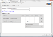
Schematic showing watershed tab for constructed stormwater pond. See Step 6.
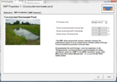
Schematic showing BMP Parameters tab for constructed stormwater pond. See Step7.
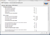
Screen shot of the BMP Summary tab for constructed stormwater pond. See Step 8.
Screen shot for the example of a constructed stormwater pond. See Step 10.


Step 7: Enter the BMP design parameters for the constructed stormwater pond into the BMP parameters tab. For this BMP all that is required is to specify the Design Level that the stormwater pond meets. This pond will be constructed to meet Design Level 2. Press the help button to review design specification required for each design level. Pollutant reduction rates are associated with each design level. A constructed stormwater pond does not provide volume reduction towards the performance goal or on an annual basis.
Step 8: Click on BMP Summary tab to view results for this BMP.
Step 9: Click on the OK button to exit the BMP properties screen.
Step 10: Click on Results tab to see overall results for the site.
Links to MIDS pages
- Overview of Minimal Impact Design Standards (MIDS)
- Performance goals for new development, re-development and linear projects
- Design Sequence Flowchart-Flexible treatment options
- Community Assistance Package
- MIDS calculator
- Performance curves for MIDS calculator
- Training and workshop materials and modules
- Technical documents
Related pages
- Overview for stormwater ponds
- Types of stormwater ponds
- Design criteria for stormwater ponds
- Design considerations for constructed stormwater ponds used for harvest and irrigation use/reuse
- Construction specifications for stormwater ponds
- Assessing the performance of stormwater ponds
- Operation and maintenance of stormwater ponds
- Cost-benefit considerations for stormwater ponds
- Calculating credits for stormwater ponds
- Stormwater wet pond fact sheet
- References for stormwater ponds
- Requirements, recommendations and information for using stormwater pond as a BMP in the MIDS calculator
This page was last edited on 23 November 2022, at 19:09.