Green roofs achieve reductions in stormwater volume compared to conventional roofs. Green roofs can effectively remove or reduce loads of many pollutants that are discharged from conventional roofs. Green roofs act as vegetated filters and provide temporary storage of rainwater or snowmelt. Water kept in storage may eventually be evapotranspired or "bleed' out of the system to the underlying drainage layer. Water reaching the drainage layer is eventually lost from the green roof system. Volume and pollutant reductions constitute stormwater credits that can be used to meet various goals (e.g. Total Maximum Daily loads (TMDLs), Minimal Impact Design Standards (MIDS) performance goals). Green roofs will achieve the greatest credit when they are properly designed, constructed and maintained.
Green roofs are used in the beginning of a treatment train. They may receive discharge from another roof, but otherwise do not receive stormwater runoff. Green roofs are excellent BMPs in ultra-urban settings where it is otherwise difficult to achieve volume and pollutant reductions due to space constraints. Since green roofs release water over a period of time following a precipitation event, they are most effective when discharge from the green roof is to a pervious surface, such as turf or a filter strip. Because green roofs effectively remove sediment, discharge from a green roof can be routed to any BMP (e.g. bioretention, infiltration basin, permeable pavement).
- The green roof is properly designed.
- The green roof was properly constructed, consistent with the design criteria.
- The green roof is properly maintained. The performance of the green roof should be regularly assessed.
Assumptions used to calculate credits may also vary with each calculator or model. To calculate credits it is important to ensure that your calculation is consistent with the assumptions made in the model or calculator you are using. Detailed discussions of assumptions may be found in user's manuals or other documentation for the model or calculator.
This section provides specific information on generating and calculating credits from green roofs for volume, TSS and phosphorus. Green roofs may also be effective at reducing concentrations of other pollutants such as metals. This article does not provide information on calculating credits for pollutants other than TSS and phosphorus, but references are provided that may be useful for calculating credits for other pollutants.
Volume credits
A green roof system acts similar to a bioretention system with an underdrain, although the underlying drainage layer may provide some volume control through storage or retarding the rate of water loss.
- Basis for volume credits
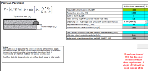
Volume credits for a green roof system are a function of the dimensions of the system, specifically the depth and storage/hydraulic conductance characteristics of the media, the area of permeable pavement, and the amount of run-on from adjacent conventional roofs. The volume credit is calculated assuming Assuming all pore space is available for infiltrating stormwater, the volume credit (Vs) is given by
\(V_s = A_s d_p n\)
where
- As = the surface area of the permeable pavement system (square feet);
- dp = the depth of the reservoir layer, equal to the area from the bottom of the underdrain to the underlying soil (do not include the surfacing thickness)(feet); and
- n = porosity of the subbase(cubic feet/cubic feet).
The volume credit shown above assumes the entire pore space is available for water storage. Although field capacity provides a more accurate estimate of the water stored in a permeable pavement system, field capacity in these systems is assumed to be very low, likely 5 percent or less (see [1]).
Often, permeable pavement will be designed to meet a specific performance goal, such as the 1.1 inch Minimal Impact Design Standards (MIDS) goal for new development sites with no restrictions or a TMDL goal for phosphorus or TSS reductions. Specifications for designing permeable pavement systems, including a discussion of how to calculate the reservoir depth, are provided in the section covering design specifications for permeable pavement.
Infiltration rates for permeable pavement are initially on the order of hundreds of inches per hour, which is much larger than the intensity that can be produced by a rain event. Infiltration rates usually exceed one inch per hour even when the pavement is substantially clogged (Smith and Hunt, 2010). Sites that receive run-on from poorly maintained or disturbed areas had the lowest infiltration rate in a study by Bean et al. 2007. However, the infiltration rates at these sites were still high relative to rainfall intensities.
If a particular storm event exceeds the design storm event, the volume of water infiltrated will exceed the design volume of the permeable pavement system. This is the result of water infiltrating into the underlying soil as precipitation or runoff water continues to be delivered to the system after the design volume has been exceeded. For example, if the performance goal is 1.1 inches and the rain event is 2.0 inches, some of the excess 0.9 inches will be captured by the permeable pavement system. This additional volume infiltrated will be greater for long duration, lower intensity storms compared to a short duration high intensity event. On an annual basis, this additional volume is relatively small.
In a system with an underdrain at the bottom, water will infiltrate at a rate dependent on the underlying soil. The volume infiltrated is equal to the infiltration rate multiplied by the time that infiltration occurs. The length of time for a system to drain is controlled by the spacing of underdrains.
Models and calculators for calculating permeable pavement volume credits
The models and calculators discussed below are widely utilized within the stormwater community and are therefore appropriate for calculating volume credits provided the model assumptions are met and the permeable pavement is properly designed, constructed and maintained.
