Difference between revisions of "Infiltration trench"
| Line 117: | Line 117: | ||
| − | |||
| − | |||
| − | |||
| − | |||
| − | |||
| − | |||
==References== | ==References== | ||
Revision as of 16:54, 7 March 2013
The anticipated construction period for this page is January through March, 2013
Infiltration Overview
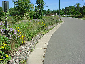
Natural or constructed depressions located in permeable soils that capture, store and infiltrate the volume of stormwater runoff associated with a particular design event.
Infiltration trench articles
- Overview for Infiltration trench
- Types of InfiltratioInfiltration trench
- Design criteria for Infiltration trench
- Construction specifications for Infiltration trench
- Operation and maintenance of Infiltration trench
- Cost-benefit considerations for Infiltration trench
- External resources for Infiltration trench
- References for Infiltration trench
Design Criteria:
- Contributing drainage area
- Underlying soil types
- Depth to the water table, bedrock or other impeding layer
- Proximity to buildings, drinking water supplies, Karst features, etc.
- Source of stormwater runoff
Benefits
- Reduces volume of stormwater runoff
- Increases ground water recharge
- Improves surface water quality
- Provides thermal benefits (e.g. to cold water fisheries)
- Mimics pre-development hydrology
Limitations
- Unusual construction considerations
- Potential for ground water contamination
- Tendency to lose effectiveness over time due to clogging – if not properly constructed or maintained
- Not recommended for areas with steep slopes
- May require landscaping: consideration should be given to periods on inundation and drought
Description
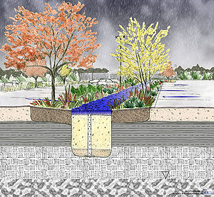
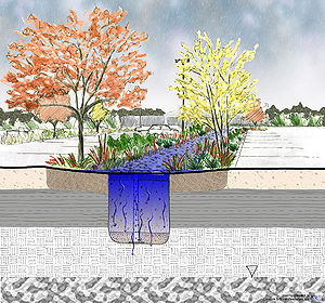
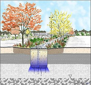
In general terms, infiltration systems can be described as natural or constructed depressions located in permeable soils that capture, store and infiltrate stormwater runoff within 48 hours. These depressions can be located at the surface of the ground (e.g. infiltration basin) or they can be designed as underground facilities (e.g. structural chamber or excavated pit filled with aggregate such as an infiltration trench). Typically, infiltration systems are designed with one or more pre-treatment facilities or they are designed as off-line facilities.
Dry wells and Trenches should be designed to handle the smaller, more frequent rainfall events. Stormwater associated with the larger rainfall events should bypass these practices by a separate pipe or an overflow device. Infiltration basins and underground infiltration systems should be designed to handle both the water quality volume and as the water quantity volume.
Infiltration systems can be designed to address a number of stormwater management issues including: water quality, stormwater runoff reduction, flow attenuation, thermal impacts to cold water fisheries, and groundwater recharge.
Maintenance Requirements
- Establishment of native vegetation may require weeding, watering, pumping, replacement of plants and tree/shrub trimming
- Inspection and removal of sediment accumulation
- Street sweeping of impervious areas adjacent to infiltration practices
- Avoid the application of fertilizer or herbicide in or near infiltration practices
SITE FACTORS
- Max Drainage Areas: Dry Well/ Trench/ Basin = 1/ 5/ 50 Acres
- Max. Site Slope = 20 percent
- Min. Depth to Bedrock = 3 feet
- Min. Depth to Seasonally High Water Table = 3 feet
- NRCS Soil Type *C & D soils have limited infiltration ability but can be used to match predevelopment conditions = A,B,C*,& D
- Freeze/ Thaw Suitability = Poor - Good
- Potential Hotspot Runoff = NO
MANAGEMENT SUITABILITY
- Water Quality (Vwq) = High
- Med. Channel Protection (Vcp)
- Overbank Flood Protection (Vp10) = Low/Med.
- Extreme Flood Protection (Vp100) = Low
- Recharge Volume (Vre) = High
MECHANISMS
- Screening/ Filtration
- Temperature Control
- Transpiration *if vegetated
- Soil Adsorption
- Biological/ Micro. Uptake
POLLUTION REMOVAL*
- Total Suspended Solids (TSS) = 100 percent
- Nutrients - Total Phosphorus/ = 100 percent
- Total Nitrogen = 100 percent
- Metals - Cadmium, Copper, Lead, and Zinc = 100 percent
- Pathogens - Coliform, Streptococci, E. Coli = 100 percent
- Toxins - Hydrocarbon = 100 percent
Pollution removal addresses only the impact on surface water, as there could be some transfer of pollution to the soil layer and groundwater.
Suitability
General
Stormwater infiltration practices capture and temporarily store stormwater before allowing it to infiltrate into the soil. Design variants include; the infiltration basin, the infiltration trench, the dry well and the underground infiltration system. As the stormwater penetrates the underlying soil, chemical, biological and physical processes remove pollutants and delay peak stormwater flows.
Infiltration practices are applicable to sites with naturally permeable soils and a suitable distance to the seasonally high groundwater table, bedrock or other impermeable layer. They may be used in residential and other urban settings where elevated runoff volumes, pollutant loads, and runoff temperatures are a concern. In applications where the stormwater runoff has a particularly high pollutant load or where the soils have very high Infiltration rates, a significant amount of pre-treatment should be provided to protect the groundwater quality. Sources that include potential stormwater should not be introduced to Infiltration systems. Sources that include potential stormwater hotsposts (PSH) should not be introduced to Infiltration areas.
Function Within Stormwater Treatment Train
Infiltration practices may be located at the end of the treatment train or they can be designed as off-line configurations where the water quality volume is diverted to the infiltration practice. In any case, the practice may be applied as part of a stormwater management system to achieve one or more of the following objectives:
- Reduce stormwater pollutants
- Increase groundwater recharge
- Decrease runoff peak flow rates
- Decrease the volume of stormwater runoff
- Preserve base flow in streams
- Reduce thermal impacts of runoff.
MPCA Permit Applicability
One of the goals of this Manual is to facilitate understanding of and compliance with the MPCA General Stormwater Permit for Construction Activity (MN R100001), commonly called the Construction General Permit (CGP), which includes design and performance standards for permanent stormwater management systems. These standards must be applied in all projects in which at least one acre of new impervious area is being created, and the permit stipulates certain standards for various categories of stormwater management practices.
For regulatory purposes, infiltration practices fall under the “Infiltration / Filtration” category described in Part III.C.2 of the permit. If used in combination with other practices, credit for combined stormwater treatment can be given as described in Part III.C.4. Due to the statewide prevalence of the MPCA permit, design guidance in this section is presented with the assumption that the permit does apply. Also, although it is expected that in many cases infiltration will be used in combination with other practices, standards are described for the case in which it is a stand alone practice.
The following terms are thus used in the text to distinguish various levels of stormwater pond design guidance:
REQUIRED: Indicates design standards stipulated by the MPCA Permit (or other consistently applicable regulations).
HIGHLY RECOMMENDED: Indicates design guidance that is extremely beneficial or necessary for proper functioning of the infiltration practice, but is not specifically required by the MPCA permit.
RECOMMENDED: Indicates design guidance that is helpful for infiltration performance but not critical to the design.
Of course, there are situations, particularly retrofit projects, in which an infiltration facility is constructed without being subject to the conditions of the MPCA permit. While compliance with the permit is not required in these cases, the standards it establishes can provide valuable design guidance to the user. It is also important to note that additional and potentially more stringent design requirements may apply for a particular infiltration facility, depending on where it is situated both jurisdictionally and within the surrounding landscape.
Of course, there are situations, particularly retrofit projects, in which an infiltration facility is constructed without being subject to the conditions of the MPCA permit. While compliance with the permit is not required in these cases, the standards it establishes can provide valuable design guidance to the user. It is also important to note that additional and potentially more stringent design requirements may apply for a particular infiltration facility, depending on where it is situated both jurisdictionally and within the surrounding landscape.
References
Bouwer, H. and R. C. Rice. 1989. Effect of Water Depth in Ground-water Recharge Basins on Infiltration. Journal of Irrigation and Drainage Engineering, Vol. 115, No. 4, pp. 556-567.
Georgia Stormwater Management Manual. 2001.
Glover, R., 1960. Mathematical Derivations as Pertain to Ground-water Recharge. Report CER60REG70. Agricultural Research Service, USDA, Fort Collins, Colorado. 81 pp.
Hantush, M., 1967. Use of Soil Texture, Bulk Density and Slope of water Retention Curve to Predict Saturated Hydraulic Conductivity. Water Resources Research, 3(1): 227-234.
Rawls, W., D. Brakensiek, and K. Saxton, 1982. Estimation of Soil Water Properties, Transactions of the American Society of Agricultural Engineers. Vol. 25, No. 5, pp. 1316 – 1320 and 1328.
Rawls, W., D. Giminez, and R. Grossman, 1998. Use of Soil Texture, Bulk Density and Slope of water Retention Curve to Predict Saturated Hydraulic Conductivity, ASAE. Vol. 41(4), pp. 983 – 988.
Metropolitan Council Urban Small Sites Best Management Practice Manual. 2001.
Minnesota Pollution Control Agency Stormwater Best Management Practices Manual. 2000.
Natural Resources Conservation Service, 1986. Urban Hydrology for Small Watersheds, Technical Release 55 (TR-55).
South Washington Watershed District (SWWD), 2005. 2004 Infiltration Monitoring Program Final Report. Emmons and Olivier Resources, Inc.
>United States Department of Agriculture Natural Resources Conservation Service. TR-55, Urban Hydrology for Small Watersheds. Washington D.C., 1975.
U.S. Department of Agriculture, Natural Resources Conservation Service, 2005. National Soil Survey Handbook, title 430-VI. (Online) Available: http://soils.usda.gov/technical/handbook/.
U.S. Environmental Protection Agency, When are Storm Water Discharges Regulated as Class V Wells, June 2003
University of Wisconsin – Extension Wisconsin Storm Water Manual: Technical Design Guidelines for Storm Water Management Practices. 2000.
Winer, R. 2000. National Pollutant Removal Performance Database.
Wisconsin Department of Natural Resources Site Evaluation for Stormwater Infiltration Conservation Practice Standard 1002. 2004.
Wisconsin Department of Natural Resources Infiltration Basin Conservation Practice Standard 1003. 2004.
Wisconsin Department of Natural Resources. Personal conversation with Roger Bannerman. July 2005.


