Difference between revisions of "Stormwater management for solar projects and determining compliance with the NPDES construction stormwater permit"
| Line 98: | Line 98: | ||
The performance goal, considering a single panel, is 5.73 cubic feet for panels adjacent to turf access areas and 12.36 cubic feet for panels adjacent to gravel areas. The volume credits are summarized below. | The performance goal, considering a single panel, is 5.73 cubic feet for panels adjacent to turf access areas and 12.36 cubic feet for panels adjacent to gravel areas. The volume credits are summarized below. | ||
*B soil adjacent to turf access roads: credit is 3.89 cubic feet, 67.9 percent of performance goal, with 1.84 cubic feet remaining to be treated | *B soil adjacent to turf access roads: credit is 3.89 cubic feet, 67.9 percent of performance goal, with 1.84 cubic feet remaining to be treated | ||
| − | *B soil adjacent to gravel roads: credit is 6. | + | *B soil adjacent to gravel roads: credit is 6.83 cubic feet, 55.3 percent of performance goal, with 5.52 cubic feet remaining to be treated |
To compute the remaining volume requiring treatment, the number of panels adjacent to turf access roads or gravel access roads must be known. | To compute the remaining volume requiring treatment, the number of panels adjacent to turf access roads or gravel access roads must be known. | ||
*There are 70 panels adjacent to turf access roads. 70 panels times 1.84 cubic feet per panel = 128.8 cubic feet. | *There are 70 panels adjacent to turf access roads. 70 panels times 1.84 cubic feet per panel = 128.8 cubic feet. | ||
Revision as of 18:11, 2 August 2018
Construction projects need to have consideration of the quantity of stormwater retained at the construction site. Estimating stormwater retained for a photovoltaic solar farm project can be challenging because the panels are impervious but the area beneath the panels is often pervious. The following methodology and guidelines are recommended for determining the quantity of stormwater retained at these types of solar panel projects.
Link to Excel calculator for computing volumes: File:Solar panel calculator.xlsx
Contents
Description of hydrologic processes at solar panel projects
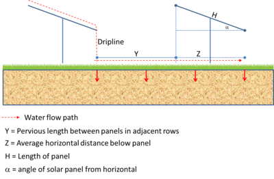
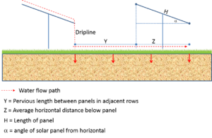
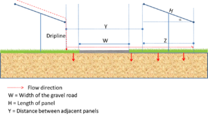
Rain falls on a solar panel, which is impervious. The rain runs across the panel to the dripline, where it falls to the underlying surface. This water can infiltrate or run off downslope to the next panel. Considering the schematic to the right, runoff water passing across a length of (Y + Z) can infiltrate. Y is the downslope length from the dripline to the beginning of the next panel. The surface under Y is pervious with well maintained vegetation and receives direct rainfall in addition to runoff from the upslope panel. Water that runs across the land surface from one dripline to the next dripline that does not infiltrate is considered to be the runoff.
All construction projects disturbing one or more acres of land must apply for the NPDES stormwater permit for construction activities, issued by the Minnesota Pollution Control Agency. The NPDES construction stormwater permit (CGP) requires stormwater management practices to be designed to treat a volume of water (referred to as the water quality volume) based the amount of impervious surfaces being constructed. Since the standard calculation for the water quality volume (1 inch times the impervious surface) required by the CGP doesn’t recognize the vegetated surface left in place under the panels, the calculation may be done using the disconnected impervious credit described on this page. For solar installations, the remaining water quality volume after applying the credit will still need to be treated using more traditional stormwater management practices.
Calculations
Z is the average horizontal length beneath the panel. The area under the panel, which would be Z times the width of the panel, is pervious with well maintained vegetation and does not receive direct rainfall. Since the panel angle may change in response to sun angle, the average horizontal length Z must be computed. Z represents the average horizontal length, not the length at the average horizontal angle. For example, if the angle varies between 30 and 60 degrees, the average horizontal length for a 10 foot long solar panel will be 6.83 feet (not 7.07 feet for a 45 degree angle). The length, Z, can be computed using the following equation.
\( Z = (COS(α max)H + COS(α min)H) / 2 \)
In order to determine the total impervious surface area for the project, the Z dimension should be used. This method will be used to determine the total water quality volume that must be treated for permitting requirements. The total solar panel impervious surface for the project = Z times the panel width times the number of panels.
The amount of infiltration is calculated using the methodology described in Recommended credits for impervious surface disconnection. Modeling used to develop this approach was performed to quantify the runoff reduction achieved from redirecting runoff from impervious areas to pervious areas of varying size and soil type. The long-term, 35-year continuous simulation XP-SWMM model developed in support of the MIDS performance goal development (Barr, 2011) was modified to represent watersheds with varying impervious to pervious ratios and hydrologic soil types of A, B, C, and D. See the link above for more detailed discussion.
Since the entire solar array is not a continuous impervious surface, the MPCA has chosen to modify the calculations to account for infiltration for a single panel. Total volumes can be calculated by multiplying the results for a single panel by the number of panels being considered. To make the calculation, the following information is needed.
- Soil type - Hydrologic Soil Group A, B, C, or D
- Area of impervious surface, which is the same as the area of a solar panel. This will equal the average horizontal distance of the panel, Z, multiplied by the width of the panel.
- Area of pervious surface - this equals the distance (Y + Z) times the width of the panel
Calculations can be made using this Excel file: File:Solar panel calculator.xlsx
This last output on this calculator will show the remaining water quality volume to be treated for an individual panel. This may be accomplished using more traditional stormwater management methods including but not limited to:
- Constructed shallow depresions for Infiltration (with or without an underdarin)
- Natural depressions on the landscape that infiltrate
- Stormwater retention ponds
- Vegetated swales
- Swales with check dams to create storage and promote infiltration
Assumptions and guidance
The following are assumptions or recommended practices for applying the above methodology.
- Projects must minimize earth disturbance and grading activities where natural vegetation cover is preserved and/or restored. Utilizing low impact construction techniques is encouraged. Projects that are unable to minimize disturbance or grading activities may employ soil/landscape restoration and soil amendment. Vegetation cover has 90 percent or better uniform coverage.
- A meadow condition is preferable, particularly for slopes between 5 and 10 percent.
- Mowed areas, where approvable, should be kept to 4 inch minimum height.
- Vegetated areas will not be subject to chemical fertilization or herbicides/pesticides except for those applications that are necessary to get vegetation established and which follow an approved Erosion and Sediment Pollution Control Plan.
- Individual photovoltaic panels within an array are arranged in a fashion that
- allows the passage of runoff between each module thereby minimizing the creation of concentrated runoff and
- allows the growth of vegetation beneath and between arrays.
- Structures/foundations for ground mounted solar panels should be included as impervious surfaces.
- The lowest vertical clearance of the solar array is at an elevation of 10 feet or less from the ground, but is also at an adequate height to promote vegetative growth below the array. If elevation is greater than 10 feet, BMPs will be necessary to prevent/control erosion and scour along the drip line or otherwise provide energy dissipation.
- Gravel (e.g. gravel access roads) is considered impervious cover.
- All impervious areas associated with roadways, solar panel posts or foundations, and support buildings will need to follow normal protocol for post-construction stormwater management.
- The minimum pervious distance downslope of the last array of solar panels must be equal to (Y+Z).
Example calculations
Two examples are included to demonstrate how calculations are made. The first example is simplistic, involving a single soil type and permeable access roads. The second example includes three soil types and some impermeable gravel access roads.
Example 1
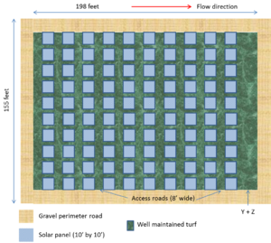
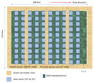
A solar farm consists of a 10 by 10 array of solar panels (100 total panels). Each panel is 10 feet long by 10 feet wide. The entire area, excluding perimeter roads, is well-maintained turf. Between each column of panels is an 8 foot access area consisting of turf. The perimeter of the solar farm consists of 15 foot wide gravel roads. The soil is Hydrologic Group B (SM), having an infiltration rate of 0.45 inches per hour.
The initial calculation is made for 1 solar panel. Each panel is assumed to rotate between 30 and 60 degrees, giving an average length of each panel of 6.83 feet. Using the dimensions shown in the figure to the right, the length Z is the length beneath each solar panel, or 6.83 feet. The length Y is the width of the vegetated access (8 feet) plus the difference between the horizontal and average lengths of the solar panels (10 minus 6.83 feet or 3.17 feet), for a length of 11.17 feet. The pervious length is Y + Z or 18 feet. Note that the pervious length could also be calculated simply as the width of each panel (10 feet) plus the distance between panels (8 feet).
Using the calculator developed for this application (File:Solar panel calculator.xlsx), the following inputs are needed.
- Soil - Hydrologic Soil Group B
- Pervious area - this equals Y + Z (18 feet) times the width of each panel (10 feet) or 180 square feet
- Impervious area - this equals Z (6.83 feet) times the width of each panel (10 feet) or 68.3 square feet
- The runoff depth from pervious areas, equal to 5.7 inches for a B soil
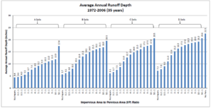
- The redirected runoff from a solar panel. The calculator automatically calculates the impervious to pervious ratio (I/P ratio), which for this example is 0.379. Using the figure in the spreadsheet (also shown to the right), the runoff from redirected impervious must be interpolated since the curve shows a value of 6.8 inches for an I/P ratio of 0.5 and 6.1 inches for an I/P ratio of 0.2. Assuming a linear curve, the resulting redirected runoff from a solar panel is 6.52 inches. NOTE this term is also called average annual runoff depth.
- Runoff depth from the solar panel equal to 22.5 inches
- Performance goal equals 1 inch (for compliance with the Construction Stormwater General Permit)
The performance goal, considering a single panel, is 5.69 cubic feet. The volume credit for this scenario is 3.86 cubic feet, meaning 67.8 percent of the performance goal is achieved. The remaining volume to be treated is 1.83 cubic feet.
Considering the entire site (100 panels plus gravel roads), the remaining volume to be treated is equal to the runoff from the impervious gravel roads plus runoff from all 100 solar panels. Runoff from the panels is 100 times 1.83 cubic feet per panel, for a volume of 183 cubic feet. For a performance goal of 1 inch, runoff from the gravel roads is 882.5 cubic feet (two 15 foot wide, 155 foot long gravel roads, and two 15 foot wide, 198 foot long gravel roads). The remaining volume to be treated is therefore 183 + 882.5 cubic feet, or 1065.5 cubic feet.
Note that if this example was for an A soil, 82.1 percent of the performance goal would have been achieved (4.68 cubic feet treated toward the performance goal of 5.73 cubic feet). If the example was for a C soil, 66.3 percent of the performance goal would have been achieved (a credit of 3.79 cubic feet toward the performance goal of 5.73 cubic feet). If the example was for a D soil, 57.3 percent of the performance goal would have been achieved (a credit of 3.28 cubic feet toward the performance goal of 5.73 cubic feet).
Example 2
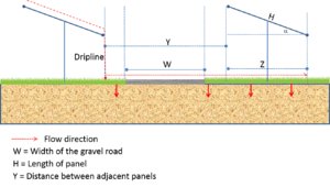
A solar farm consists of a 10 by 10 array of solar panels (100 total panels). Each panel is 10 feet long by 10 feet wide. The entire area, excluding perimeter gravel roads and three interior gravel access roads, is well-maintained turf. The gravel roads are considered to be impervious. The area between each column of panels consists either of an 8 foot wide turf access area or an 8 foot wide impermeable gravel area. The perimeter of the solar farm consists of 15 foot wide gravel roads. The soil is Hydrologic Group B (SM), having an infiltration rate of 0.45 inches per hour.
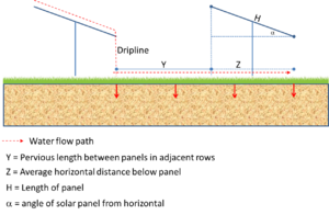
The initial calculation is made for 1 solar panel. However, two calculations must be made separately for solar panels adjacent to turf access areas and panels adjacent to gravel access roads. Each panel is assumed to rotate between 30 and 60 degrees, giving an average length of each panel of 6.83 feet. For panels adjacent to turf access areas, and using the dimensions shown in the figure to the right, the length Z is the length beneath each solar panel, or 6.83 feet. The length Y is the width of the access road (8 feet) plus the difference between the horizontal and average lengths of the solar panels (10 minus 6.83 feet or 3.17 feet), for a length of 11.17 feet. The pervious length is Z + Y or 18 feet. Note that if the entire area between panels is pervious, the pervious length is simply the distance between panels (Y) plus the width of each panel (H), or 10 + 8 = 18 feet. For panels adjacent to gravel access roads, the width of the gravel road must be counted as impervious surface rather than pervious surface. So the impervious length is Z (6.83 feet) plus the width of the road (8 feet) or 14.83 feet. The pervious length is the average width of the solar panel (6.83 feet), plus the distance between panels when the panels are at their average rotation (11.17 feet), minus the width of the gravel road (8 feet), for a total pervious length of 10 feet. Note that the pervious length can also be calculated simply as the width of a solar panel, plus the distance between solar panels that are in the horizontal position, minus the width of the gravel road (10 + 8 - 8 = 10 feet).
Using the calculator developed for this application (File:Solar panel calculator.xlsx) for a solar panel adjacent to a turf access area, the inputs, calculations, and results are the same as for example 1. For a solar panel adjacent to a gravel road, the following inputs are needed.
- Soil - Hydrologic Soil Group B
- Pervious area - this equals the pervious length (10 feet) times the width of each panel (10 feet) or 100 square feet
- Impervious area - this equals the impervious length (14.83 feet) times the width of each panel (10 feet) or 148.3 square feet
- The runoff depth from pervious areas, equal to 5.7 inches for a B soil
- The redirected runoff from a solar panel. The calculator automatically calculates the impervious to pervious ratio (I/P ratio), which for this example is 1.483. Using the figure in the spreadsheet (also shown to the right), the runoff from redirected impervious must be interpolated since the curve shows a value of 8.0 inches for an I/P ratio of 1.0 and 10.1 inches for an I/P ratio of 2.0. Assuming a linear curve, the resulting redirected runoff from a solar panel is 9.01 inches. NOTE this term is also called average annual runoff depth.
- Runoff depth from the solar panel equal to 22.5 inches
- Performance goal equals 1 inch (for compliance with the Construction Stormwater General Permit)
The performance goal, considering a single panel, is 5.73 cubic feet for panels adjacent to turf access areas and 12.36 cubic feet for panels adjacent to gravel areas. The volume credits are summarized below.
- B soil adjacent to turf access roads: credit is 3.89 cubic feet, 67.9 percent of performance goal, with 1.84 cubic feet remaining to be treated
- B soil adjacent to gravel roads: credit is 6.83 cubic feet, 55.3 percent of performance goal, with 5.52 cubic feet remaining to be treated
To compute the remaining volume requiring treatment, the number of panels adjacent to turf access roads or gravel access roads must be known.
- There are 70 panels adjacent to turf access roads. 70 panels times 1.84 cubic feet per panel = 128.8 cubic feet.
- There are 30 panels adjacent to gravel access roads. 30 panels times 5.52 cubic feet per panel = 165.6 cubic feet.
Adding these values up gives 294.4 cubic feet. For a performance goal of 1 inch, runoff from the perimeter gravel roads is 882.5 cubic feet (see Example 1). Thus, the total volume needing treatment is 294.4 + 882.5 = 1176.9 cubic feet.
Example 3
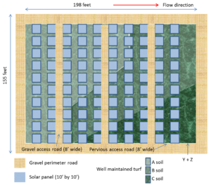
A solar farm consists of a 10 by 10 array of solar panels (100 total panels). Each panel is 10 feet long by 10 feet wide. The entire area, excluding perimeter gravel roads and three interior gravel access roads, is well-maintained turf. The gravel roads are considered to be impervious. The area between each column of panels consists either of an 8 foot wide turf access area or an 8 foot wide impermeable gravel area. The perimeter of the solar farm consists of 15 foot wide gravel roads. Three soils occur on the site, including Hydrologic Soil Groups A, B, and C.
The initial calculation is made for 1 solar panel. However, six calculations must be made separately for solar panels adjacent to turf access areas (A, B, and C soils) and panels adjacent to gravel access roads. Each panel is assumed to rotate between 30 and 60 degrees, giving an average length of each panel of 6.83 feet. For panels adjacent to turf access areas, and using the dimensions shown in the figure to the right, the length Z is the length beneath each solar panel, or 6.83 feet. The length Y is the width of the access road (8 feet) plus the difference between the horizontal and average lengths of the solar panels (10 minus 6.83 feet or 3.17 feet), for a length of 11.17 feet. The pervious length is Z + Y or 18 feet. Note that if the entire area between panels is pervious, the pervious length is simply the distance between panels (Y) plus the width of each panel (H), or 10 + 8 = 18 feet. For panels adjacent to gravel access roads, the width of the gravel road must be counted as impervious surface rather than pervious surface. So the impervious length is Z (6.83 feet) plus the width of the road (8 feet) or 14.83 feet. The pervious length is the average width of the solar panel (6.83 feet), plus the distance between panels when the panels are at their average rotation (11.17 feet), minus the width of the gravel road (8 feet), for a total pervious length of 10 feet. Note that the pervious length can also be calculated simply as the width of a solar panel, plus the distance between solar panels that are in the horizontal position, minus the width of the gravel road (10 + 8 - 8 = 10 feet).
Using the calculator developed for this application (File:Solar panel calculator.xlsx) for a solar panel adjacent to a turf access area, the inputs, calculations, and results are the same as for example 1. For a solar panel adjacent to a gravel road, the following inputs are needed.
- Soil - A, B, or C
- Pervious area - this equals the pervious length (10 feet) times the width of each panel (10 feet) or 100 square feet
- Impervious area - this equals the impervious length (14.83 feet) times the width of each panel (10 feet) or 148.3 square feet
- The runoff depth from pervious areas, equal to 4.4 inches for an A soil, 5.7 inches for a B soil, and 6.1 inches for a C soil
- The redirected runoff from a solar panel. The calculator automatically calculates the impervious to pervious ratio (I/P ratio), which for this example is 1.483. Using the figure in the spreadsheet (also shown to the right), the runoff from redirected impervious must be interpolated since the curve shows values for I/P ratios of 1.0 and 2.0. Assuming a linear curve, the resulting redirected runoff from a solar panel is 6.05 inches for an A soil, 9.0 inches for a B soil, and 9.8 inches for a C soil. NOTE this term is also called average annual runoff depth.
- Runoff depth from the solar panel equal to 22.5 inches
- Performance goal equals 1 inch (for compliance with the Construction Stormwater General Permit)
The performance goal, considering a single panel, is 5.73 cubic feet for panels adjacent to turf access areas and 12.36 cubic feet for panels adjacent to gravel areas. The volume credits are summarized below.
- A soil adjacent to turf access roads: credit is 4.68 cubic feet, 81.7 percent of performance goal, with 1.05 cubic feet remaining to be treated
- A soil adjacent to gravel roads: credit is 9.30 cubic feet, 75.3 percent of performance goal, with 3.06 cubic feet remaining to be treated
- B soil adjacent to turf access roads: credit is 3.89 cubic feet, 67.9 percent of performance goal, with 1.84 cubic feet remaining to be treated
- B soil adjacent to gravel roads: credit is 6.84 cubic feet, 55.3 percent of performance goal, with 5.52 cubic feet remaining to be treated
- C soil adjacent to turf access roads: credit is 3.28 cubic feet, 57.3 percent of performance goal, with 2.45 cubic feet remaining to be treated
- C soil adjacent to gravel roads: credit is 6.19 cubic feet, 50.1 percent of performance goal, with 6.17 cubic feet remaining to be treated
To compute the remaining volume requiring treatment, the number of panels in each soil type must be known.
- There are 30 panels adjacent to turf access roads in HSG A. 30 panels times 1.05 cubic feet per panel = 31.5 cubic feet.
- There are 15 panels adjacent to gravel access roads in HSG A. 15 panels times 3.05 cubic feet per panel = 45.9 cubic feet.
- There are 26 panels adjacent to turf access roads in HSG B. 26 panels times 1.84 cubic feet per panel = 47.84 cubic feet.
- There are 11 panels adjacent to gravel access roads in HSG B. 11 panels times 5.52 cubic feet per panel = 60.72 cubic feet.
- There are 14 panels adjacent to turf access roads in HSG C. 14 panels times 2.45 cubic feet per panel = 34.3 cubic feet.
- There are 4 panels adjacent to gravel access roads in HSG C. 4 panels times 6.17 cubic feet per panel = 24.68 cubic feet.
Adding these values up gives 244.9 cubic feet. For a performance goal of 1 inch, runoff from the perimeter gravel roads is 882.5 cubic feet (see Example 1). Thus, the total volume needing treatment is 244.9 + 882.5 = 1127.4 cubic feet.
