Difference between revisions of "Overview for green roofs"
m |
|||
| Line 3: | Line 3: | ||
==Function within stormwater treatment train== | ==Function within stormwater treatment train== | ||
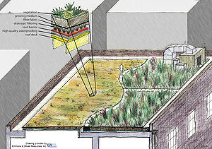
[[File:green roof schematic.jpg|thumb|300px|alt=illustration showing typical green roof sections|<font size=3>Schematic showing the different components of a green roof. Thicknesses of some layers vary with the design (e.g. extensive vs. intensive roofs).</font size>]] | [[File:green roof schematic.jpg|thumb|300px|alt=illustration showing typical green roof sections|<font size=3>Schematic showing the different components of a green roof. Thicknesses of some layers vary with the design (e.g. extensive vs. intensive roofs).</font size>]] | ||
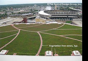
| − | [[File:Vegetation free zones at Target Center Green Roof, Minneapolis, MN.jpg|thumb|300px|alt=photo of green roof on the Target Center in Minneapolis, MN|<font size=3>Green roof on the Target Center in Minneapolis Minnesota. Note the vegetation free zones.</font size>]] | + | [[File:Vegetation free zones at Target Center Green Roof, Minneapolis, MN.jpg|thumb|300px|alt=photo of green roof on the Target Center in Minneapolis, MN|<font size=3>Green roof on the Target Center in Minneapolis Minnesota. Note the vegetation free zones. Image Courtesy of The Kestrel Design Group, Inc.</font size>]] |
Green roofs occur at the beginning of [[Using the treatment train approach to BMP selection |stormwater treatment trains]]. Green roofs provide filtering of suspended solids and pollutants associated with those solids, although [[Glossary#T|total suspended solid]] (TSS) concentrations from traditional roofs are generally low. Green roofs provide both volume and rate control, thus decreasing the stormwater volume being delivered to downstream [[Glossary#B|Best Management Practices]] (BMPs). | Green roofs occur at the beginning of [[Using the treatment train approach to BMP selection |stormwater treatment trains]]. Green roofs provide filtering of suspended solids and pollutants associated with those solids, although [[Glossary#T|total suspended solid]] (TSS) concentrations from traditional roofs are generally low. Green roofs provide both volume and rate control, thus decreasing the stormwater volume being delivered to downstream [[Glossary#B|Best Management Practices]] (BMPs). | ||
Revision as of 20:21, 1 July 2013
The anticipated review period for this page is June through September 2013
Contents
Function within stormwater treatment train
Green roofs occur at the beginning of stormwater treatment trains. Green roofs provide filtering of suspended solids and pollutants associated with those solids, although total suspended solid (TSS) concentrations from traditional roofs are generally low. Green roofs provide both volume and rate control, thus decreasing the stormwater volume being delivered to downstream Best Management Practices (BMPs).
MPCA permit applicability
One of the goals of this Manual is to facilitate understanding of and compliance with the MPCA Construction General Permit (CGP), which includes design and performance standards for permanent stormwater management systems. Standards for various categories of stormwater management practices must be applied in all projects in which at least one acre of new impervious area is being created.
Although few roofs will meet or exceed the one acre criteria, roofs can contribute to the one acre determination at a site. Therefore, green roofs can be used in combination with other practices to provide credit for combined stormwater treatment, as described in Part III.C.4 of the permit. Due to the statewide prevalence of the MPCA permit, design guidance for green roofs is presented with the assumption that the permit does apply. Also, although it is expected that in many cases the green roof practice will be used in combination with other practices, standards are described for the case in which it is a stand-alone practice.
Retrofit suitability
Green roofs are an ideal and potentially important BMP in urban retrofit situations where existing stormwater treatment is absent or limited. Green roofs can be particularly important in ultra-urban settings.
Special receiving waters suitability
The following table provides guidance regarding the use of green roofs in areas upstream of special receiving waters. This table is an abbreviated version of a larger table in which other BMP groups are similarly evaluated. The corresponding information about other BMPs is presented in the respective sections of this Manual.
Design restrictions for special waters - green roofs
Water quantity treatment
A portion of rain that falls on green roofs is stored in the green roof media and eventually lost to evapotranspiration. Green roofs therefore provide water quantity treatment.
Green roof hydrology
Rain that falls on a green roof soaks into the soil (growing media) and
- is evaporated or transpired from the growing media and plants back into the atmosphere, or
- percolates through the growing medium into the drainage layer under the growing medium and eventually to the roof drains.
Surface runoff almost never occurs on a green roof except during massive rainfalls. The FLL (Forschungsgesellschaft Landschaftsentwicklung Landschaftsbau e.v.) guidelines for saturated hydraulic conductivity of growing medium for multi-course extensive green roofs, for example, is 0.024 to 2.83 inches per minute. Green roofs are analogous to thin groundwater systems. Discharge from a green roof is best understood as ‘groundwater baseflow’ from this system. This is apparent when you consider the time delay between rainfall peaks and discharge peaks on green roofs. For a green roof area of 5,000 square feet the delay may be 60 minutes, versus 15 minutes if a surface flow ‘time of concentration’ was calculated using the Manning formula, or similar. Green roofs do not have curve numbers, since nothing infiltrates.
Times of concentration in the context of TR-55, do not apply to green roofs. There should be no surface flow under normal conditions. Rather, the rate at which water is discharged from the roof depends on the design of the subsurface drainage zone. The appropriate parameter is transmissivity.
Green roof growing media water storage potential and evapotranspiration (ET) potential are dynamic. The pattern of water uptake and release from the surface media can be summarized as follows.
- Initially all moisture is absorbed and no underflow occurs.
- After about ½ of the maximum water capacity (MWC) is satisfied, the first ‘break through’ of precipitation occurs and underflow begins.
- The media continues to absorb more water, with increasing efficiency, even as percolation continues.
- Finally, the capacity of the media to hold water is overwhelmed and the underflow rate will approach rainfall rate for the first time.
- As the rainfall rate decreases, the moisture content will continue to drop until it attains the MWC (typically 30 to 40 percent by volume).
- After the rainfall has stopped, water will continue to bleed out of the green roof for an extended period. At the same time water is continuously lost to the atmosphere via direct evaporation and plant evapotranspiration. Depending on the type of media, this process may last for days.
- Eventually, underflow will end. The moisture remaining at this point is associated with field capacity (typically 15 to 20 percent by volume). This water will be slowly removed from the media through evapotranspiration of the plants (adapted from Miller, 2003).
ET rates also vary over time, depending on climatic conditions, soil moisture, and vegetation vigor, cover, and species. Several studies have shown rapid water loss through ET immediately after a rain event and much slower ET rates starting 5 to 10 days after soil was saturated, when plants need to start conserving water to survive (Voyde et. al., 2010, Rezaei et. al., 2005).
Preliminary research results indicate that transmissivity of the drainage layer significantly affects how much rain a green roof retains and evapotranspires. Transmissivity of typical geocomposite drain sheets ranges from 0.050 to 0.200 square meters per second ([ASTM] D4716 and ASTM 2396), which is 50 times greater than that of a typical 2 inch granular drainage layer (0.001 to 0.004 square meters per second). Lower transmissivity results in longer residence times for rainfall in the green roof. This translates to more efficient water absorption and longer delay in peak runoff rate. Preliminary research results indicate that green roofs that have a drainage layer with lower transmissivity have significantly higher ET rates.
A model that accounts for these dynamic processes is needed to accurately reflect green roof hydrology. However, studies and field experience have found that maximum media water retention (MMWR), the quantity of water held in a media at the maximum media density of the media using the ASTM E2399 standard testing procedure, provides a very approximate estimate of event green roof runoff retention potential. The aggregated effect of storage and ET processes in green roofs can result in annual runoff volume reductions of 60 percent or more. However, the increase in retention storage potential with increasing soil depth is not linear. This is a consequence of the non-uniform moisture distribution in the soil column. Consequently increasing media thickness above 4 to 6 inches does not provide significant increase in retention storage potential in many instances.
Water retention by green roofs
Studies show that, compared to traditional hard roofs, green roofs:
- decrease runoff peak discharge (eg. Berghage et. al., 2010; Carter and Rasmussen, 2006);
- delay peak runoff (eg. Carter and Rasmussen, 2006; Van Woert et. al., 2005; Berghage et. al., 2010); and
- reduce runoff volume (eg. Carter and Rasmussen, 2006; Teemusk and Mander, 2007; Van Woert et. al., 2005)
Green roof stormwater performance is affected by regional climatic conditions, storm size, rain intensity, frequency, and duration, antecedent moisture in the soil, transmissivity of drainage layer, vegetation species and diversity, length of flow path, roof size, growing medium composition and depth, and roof age.
For small rainfall events (typically less than ½ inch) little or no runoff will occur (e.g. Rowe et. al., 2003; Miller, 1998; Simmons et. al., 2008; Moran et. al., 2005). Lower intensity storms also result in greater stormwater retention than high intensity storms (Villarreal and Bengtsson, 2005). For storms of greater intensity and duration, a vegetated roof can significantly delay and reduce the runoff peak flow that would otherwise occur with a traditional roof.
Annual runoff volume reduction in northern temperate regions is regularly measured to be 50 to 70 percent when the media thickness is 3 to 6 inches (e.g. Berghage et. al., 2010; Carter and Rasmussen, 2006; Van Woert et. al., 2005; Moran et. al., 2005; Van Seters et. al., 2007; Berghage et. al., 2009). While no green roofs have been monitored for annual stormwater retention in Minnesota, green roofs in Minnesota’s climate (with shorter storms, and generally enough time to allow evapotranspiration to renew much of the soil water holding capacity between rain events) are expected to retain about 70 percent of annual runoff. Berghage et al (2010), studying an extensive green roof with 3 inches of growing medium in Chicago IL and a climate similar to Minnesota’s climate, found 74 percent annual retention over a 2 year study period that included 106 precipitation events. Higher reductions are attainable by maximizing design for stormwater retention and evapotranspiration (e.g. Compton and Whitlow, 2006).
- decrease runoff peak discharge (eg. Berghage et. al. 2010; Carter and Rasmussen, 2006);
- delay peak runoff (eg. Carter and Rasmussen, 2006; Van Woert et. al., 2005; Berghage et. al., 2010); and
- reduce runoff volume (eg. Carter and Rasmussen, 2006; Teemusk and Mander, 2007; Van Woert et. al., 2005)

