Construction stormwater treatment - dewatering, including chemical treatment and sediment filtration
This section of the manual is being developed
Dewatering is defined by the MPCA Construction Stormwater General Permit as “the removal of surface or ground water to dry and/or solidify a construction site to enable construction activity.” Dewatering usually involves using a pump to drain a trench, pit, or other low area, and can be conducted with several devices and treatments.
Water removed from a construction site is often sediment laden, which can negatively impact nearby water resources if discharged without treatment. Sediment dewatering bag filters, silt fence enclosures, sediment traps, basins, and other similar practices are generally effective at removing larger particles by settling. Smaller particles, such as clay and fine silt, tend to remain in suspension beyond the typical design retention times for these BMPs. Chemical treatment followed by sediment filtration during dewatering can further reduce turbidity and associated pollutants in discharge water.
In chemical treatment, compounds such as polymers and alum bind small clay particles and other pollutants, making their removal easier. Sediment filtration in dewatering practices involves the separation of sediment and other particles from the stormwater by passing it through a silt fence or other permeable medium that traps a high percentage of the particles. This process does not require chemical treatment but can be used in conjunction with chemical treatment.
Contents
Purpose and function
Construction sites often have trenches, pits or low-lying areas, whether from the site’s existing topography or from excavated areas, that can fill with rain water. This water often needs to be removed and discharged from the area to allow work to continue as scheduled, and to prevent accidents and damage to the structural integrity of the site. Dewatering also may be necessary to remove accumulated water and sediment from sediment traps and basins to ensure their effectiveness throughout the project, and at the end of the project prior to removing sediment control measures. Dewatering activities can produce highly turbid discharge water.
Sediment filtration and chemical treatment practices can be used to meet turbidity, or small particle, requirements that cannot be met with conventional sedimentation control treatments such as basins or berms. When used in conjunction with gravity settling, filtration can remove sediment as small as fine silt (0.5 µm). Chemical treatment occurs on a batch or flow-through basis and uses the processes of coagulation and flocculation. Chemicals such as polymers and alum destabilize the small suspended particles and cause them to flocculate into larger masses that settle out in a treatment tank or that can be removed through filtration.
Applicability
Evaluate water discharged from the site to determine turbidity, particle size, and volume. These factors guide selection and sizing of the appropriate BMP(s). Discharge small volumes of relatively clear groundwater from an excavation to a silt fence enclosure at an infiltration site. Treat flows with large (e.g., sand) particles via silt fence filtration. For trenches and pits, dewatering needs can be greatly reduced by only excavating areas where construction can be completed in hours rather than days or weeks. For example, trenching pipeline beds immediately before laying the pipe minimizes groundwater inflow to the trench, and thus the need for high-volume dewatering. Sediment concentrations in dewatering discharges from large pits and sediment basins can be reduced significantly by using floating (i.e., “skimmer”) inlet pipes that are suspended just below the surface, where water clarity is usually highest.
Chemical treatment is applicable when particles are too small and buoyant for simple settling processes or filtration and can be accomplished by either batch or flow-through treatment. This practice reliably reduces turbidity (small particles) and associated pollutants when preceded by treatment with sediment traps or basins or other sedimentation BMPs. Likewise, properly selected sediment filters used in conjunction with traditional construction stormwater BMPs removes fine sediment that contributes to turbidity. Specific treatment chemicals and chemical treatment systems must be described in the site’s SWPPP and approved by the appropriate permitting authority to ensure that treated stormwater discharged from the construction site is not toxic to aquatic organisms.The use of stormwater filtration does not require prior approval.
Site applicability
Dewatering practices are applicable to all construction sites where excess water needs to be removed and discharged, particularly excavated areas where water collects and does not otherwise drain, such as trenches, pits, sediment basins, and traps. Accumulated water and sediment must be removed from these practices during construction to ensure their effectiveness throughout the construction process.
Water pumped from low areas of construction sites can contain high concentrations of suspended soils and associated pollutants including nutrients and heavy metals, resulting in high turbidity. These fine particles may already be suspended in water or may have become suspended due to the pumping process. Dewatering discharge to surface waters is not permitted until adequate treatment is achieved such that the discharge will not negatively impact the receiving water and aquatic ecosystems. Chemical treatment and sediment filtration should be considered where turbid discharges to sensitive waters cannot be prevented using sediment basins and traps and other traditional BMPs.
Permit applicability
The MPCA Construction Stormwater General Permit has several requirements regarding sediment filtration and chemical treatment used in conjunction with dewatering activities (Section 10: Dewatering and Basin Draining).
- Section 10.2: All turbid and sediment-laden waters related to dewatering must be discharged to a temporary or permanent sediment basin on the project site unless infeasible.
- Section 10.3: Oil and grease separators or other suitable filtration devices must be used if discharge water contains oil or grease.
- Section 10.4: Permittees must discharge all water from dewatering or basin-draining activities in a manner that does not cause erosion or scour in the immediate vicinity of discharge points or inundation of wetlands in the immediate vicinity of discharge points that causes significant adverse impact to the wetland.
Additional permit language pertaining to chemical treatment is discussed below.
Specific permit language
Chemical treatment
- Section 5.22 of the MPCA Construction Stormwater General Permit (2018) states: “The SWPPP must describe any specific chemicals and chemical treatment systems used for enhancing the sedimentation process and how it achieves compliance with item 9.18.”
- Section 9.18 states: “Permittees must use polymers, flocculants, or other sedimentation treatment chemicals in accordance with accepted engineering practices, dosing specifications and sediment removal design specifications provided by the manufacturer or supplier. The permittees must use conventional erosion and sediment controls prior to chemical addition and must direct treated stormwater to a sediment control system for filtration or settlement of the floc prior to discharge.”
Discharge
- Section 10.2 states: “Permittees must discharge turbid or sediment-laden waters related to dewatering or basin draining (e.g., pumped discharges, trench/ditch cuts for drainage) to a temporary or permanent sediment basin on the project site unless infeasible. Permittees may dewater to surface waters if they visually check to ensure adequate treatment has been obtained and nuisance conditions (see Minn. R. 7050.0210, subp. 2) will not result from the discharge. If permittees cannot discharge the water to a sedimentation basin prior to entering a surface water, permittees must treat it with appropriate BMPs such that the discharge does not adversely affect the surface water or downstream properties.”
- Section 10.4 states: “Permittees must discharge all water from dewatering or basin-draining activities in a manner that does not cause erosion or scour in the immediate vicinity of discharge points or inundation of wetlands in the immediate vicinity of discharge points that causes significant adverse impact to the wetland.”
Filtration requirements
- Section 10.3 states: “If permittees must discharge water containing oil or grease, they must use an oil-water separator or suitable filtration device (e.g., cartridge filters, absorbents pads) prior to discharge.”
- Section 10.5 states: “If permittees use filters with backwash water, they must haul the backwash water away for disposal, return the backwash water to the beginning of the treatment process, or incorporate the backwash water into the site in a manner that does not cause erosion.”
Effectiveness
Various practices can be used for sediment removal from dewatering discharge. Sedimentation is primarily effective at removing larger sized particles, while filtration and chemical treatment can also remove fine particles. These approaches are less effective for dissolved, non-adsorbed metals and nutrients. Effectiveness of chemical treatment depends greatly on the pH and temperature of the treated water.
Expected performance benefits for various dewatering practices.
Link to this table
| Water quantity | |||
|---|---|---|---|
| Flow attenuation | |||
| Runoff volume reduction | |||
| Water quality | |||
| Soil erosion | |||
| Sediment control | |||
| Nutrient loading2 | |||
| Pollutant removal | |||
| Total suspended solids | |||
| Total phosphorus2 | |||
| Heavy metals | |||
| Floatables | |||
| Oil and grease | |||
1 Pretreatment via settling and/or filtration.
2 For soil-borne nutrients; i.e., not dissolved forms.
3 Benefit can be significantly improved with the use of a floating skimmer for discharge
Planning considerations
Planning considerations include the following.
- Evaluate dewatering needs and select BMPs consistent with discharge water location, turbidity, particle size, volume, and other pollutants present.
- Locate BMPs away from waterbodies and areas subject to flooding if possible.
- Plan treatment train configurations to remove large particles and attenuate flow first (e.g., silt fence/sediment traps), add flocculants next (socks, blocks, etc.), and then remove floc particles via filtration or settling.
- Size BMPs and treatment trains to handle the 2-year, 24-hour storm.
- Ensure equipment access to accommodate removal of accumulated sediment.
All appropriate safety precautions must be followed when handling chemicals, and designs must consider and minimize all hazards related to the particular chemicals used. Chemical safety equipment should be stored on site in a lockable shed and should include the chemical injector, secondary containment (for acid, caustic, buffering compound, and treatment chemical), emergency shower and eyewash, and monitoring equipment including a pH meter and turbidimeter. Any tanks or ponds should have ladders, steps, or similar features extended from top to bottom. Per Section 12.3 of the MPCA Construction Stormwater General Permit (2018), “Permittees must place… treatment chemicals under cover (e.g., plastic sheeting or temporary roofs) or protect them by similarly effective means designed to minimize contact with stormwater.”
The use of chemicals for treatment requires review and approval by the appropriate permitting authority to ensure they are not toxic to aquatic organisms. Additionally, specific chemicals and chemical treatment systems used for enhancing the sedimentation process must be described in the site’s SWPPP.
Design
Dewatering filters
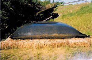
Dewatering bags, wire-reinforced silt fence enclosures, geotextiles, fiber log berms, rock berms, and other filters can be used effectively for many dewatering applications. Infiltration of small volumes of dewatering flows is also highly effective. The key to success is to ensure that 1) particles cannot pass through the selected filter, and 2) flow volumes do not overwhelm the filtering site. Follow the manufacturer’s recommendations regarding the use of dewatering bags, silt fences, geotextiles, and other filters, and monitor the filters regularly for performance and maintenance needs. Filters are often used in conjunction with chemical treatment to remove flocculated soil particles prior to final discharge. Frequent cleaning of the filter media will be required.
Sedimentation facilities
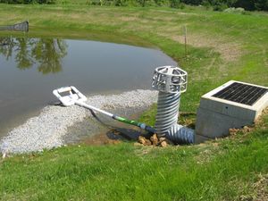
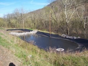
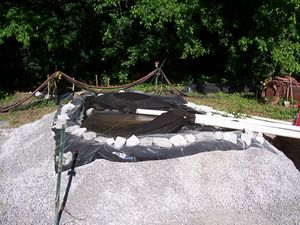
Sedimentation facilities for dewatering include wire-reinforced silt fence enclosures – which perform double duty as both filters and settling devices - sediment basins and traps, tanks, fabricated enclosures, and other settling vessels. Sedimentation facility sizing and design must consider particle size, flow volumes, and flow velocity/turbulence to ensure proper settling time and storage volume. Sedimentation facilities are often used in conjunction with chemical treatment to remove flocculated soil particles prior to final discharge.
Chemical treatment-flow-through
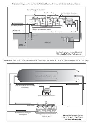
Typical construction site application of flow-through chemical treatment involves the addition of a flocculant (e.g., chitosan, polyacrylamide, etc.) to pretreated stormwater flows via contact with a polymer-containing sock or block. Pretreatment usually involves the filtration and/or sedimentation processes described above, along with minimization of non-target inputs from the site – such as upland runoff, litter, debris, and other pollutants. Chemically treated (flocculated) flows are then routed to a filter or sedimentation basin/vessel for sediment removal prior to final discharge.
Flows involving a more complex mix of challenges in terms of pH and pollutants may require more sophisticated methods for treatment. More information on advanced sediment filtration design is provided below.
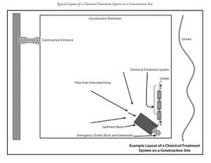
At a minimum, an advanced flow-through chemical treatment system consists of:
- a stormwater collection system,
- an untreated stormwater storage pond (such as a sediment basin), and
- a chemically enhanced sand filtration system.
As with a batch treatment system, stormwater is collected at interception point(s) on the site and diverted by gravity or pumping to a stormwater storage pond or other stormwater holding area. The stormwater is stored until chemical treatment occurs. Ensure the holding pond is large enough to provide adequate storage. Stormwater is pumped from the stormwater storage pond to the chemically enhanced sand filtration system where a coagulant is added. Adjustments to pH may be necessary before coagulant addition. The sand filtration system continually monitors the stormwater effluent for turbidity and pH. If the discharge water is out of an acceptable range for turbidity or pH, the water is returned to the stormwater pond where it will begin the treatment process again. Applicable discharge limits may be established by the MPCA Construction Stormwater General Permit or a site-specific discharge permit.
Chemical treatment-batch treatment
Dewatering flows can also be treated in batches, rather than via flow-through contact with the flocculants. Batch treatment on construction sites typically involves the use of a sediment pond, trap, or other vessel (e.g., dumpster, tank, etc.) as a site for mixing powdered or granular batches of the flocculant with known volumes of stormwater. Treated water in the basin or vessel can be discharged from the upper portion of the water column after allowing sufficient time for floc settling. Discharges of treated water can also be routed through a filter for additional sediment removal.
An engineered batch treatment system may be required in cases where complex treatment challenges exist. A typical batch chemical treatment system for these more challenging situations consists of components similar to the simpler systems:
- A stormwater collection system
- A stormwater storage pond (such as a sediment basin)
- Pumps
- A chemical feed system
- Lined treatment cells (minimum of two; can be ponds or tanks)
- System for filtering and monitoring
Prior to chemical treatment, ensure the pH of the stormwater to be treated is within the recommended range for the chemical used (typically between 6.5 and 8.5). The pH of the stormwater can be altered with the application of carbon dioxide (acidic) or a base such as sodium bicarbonate (baking soda). A batch chemical treatment system consists of four main steps.
- Coagulation: coagulants such as polymers are added to disrupt negative charges on fine particles and allow them to flocculate. Rapid mixing encourages thorough and even dispersion of the coagulant.
- Flocculation: gentle mixing is used to bind fine particles together to form larger particles that settle more rapidly.
- Clarification: settling of the particles, which is largely dependent on water temperature and water movement (currents). Warmer temperatures reduce viscosity and density and increase the rate at which particles settle. Quiescent water is necessary to allow settling and minimize resuspension of particles.
- Filtration: chemically treated stormwater is filtered to enhance removal of flocculated sediment. Monitor effluent continually for turbidity and pH to ensure treatment is acceptable.
Multiple treatment cells allow for clarification of chemically treated water in one cell while the other cell(s) is filling or emptying. Size the untreated stormwater storage system and treatment cells to hold 1.5 times the volume of runoff generated from the site during the 10-year, 24-hour storm event to minimize bypass of untreated water. Provide bypass around the chemical treatment system into a settling pond to accommodate larger storm events.
The following is a list of chemicals typically used for treating turbidity (subject to local, state, or federal requirements; the appropriate permitting authority should be contacted for additional information and conditions of use).
List of chemicals typically used for treating turbidity table
Link to this table
| Chemical Type | Chemical Name | Description |
|---|---|---|
| Polymers | Chitosan | Made from chitin. Rapidly binds to suspended sediment. Unlikely to adversely affect aquatic life. |
| Anionic Polyacrylamide (PAM) | Synthetic polymer; includes a wide variety of chemicals based on acrylamide unit. Ensure that the product selected is anionic -- cationic products are toxic to aquatic environments. Flocculate should be removed via filtration or sedimentation. | |
| Other additives | Diallyldimethyl ammonium chloride (DADMAC) | Positively charged monomer that binds negatively charged sediment particles into flocs. Can exhibit a strong aquatic toxicity. |
| Gypsum | Naturally and widely occurring mineral made up of calcium sulfate and water. | |
| Alum1 | Aluminum sulfate material widely used in water treatment industry. Often more efficient than gypsum but can acidify treated water if overdosed. | |
| Aluminum and iron chlorides1 | Cations that bridge negatively charged sediment particles, causing them to coagulate and settle. |
1Alum and aluminum and iron chlorides are also frequently used in Minnesota to coagulate soluble phosphorus out of stormwater and water bodies.
As noted above, sediment filtration can be used in conjunction with gravity settling (e.g., sediment ponds and sediment traps) or as the filtering process in sophisticated flow-through or batch chemical treatment processes. There are two main types of sediment filtration methods: rapid and slow filtration. Slow sediment filtration uses gravity to move water through a system. It is typically used on the treatment line of construction stormwater and does not have a backwash system. Rapid filtration is typically used in treating water and wastewater, as the automatic backwash system allows for higher hydraulic flow rates.
Filters must be designed to control the treated stormwater velocity and peak volumetric flow rate from the system to reduce erosion and sedimentation at the outlet. Sizing of the stormwater pond should be consistent with sediment basin standards.
There are several types of filters that have varying turbidity reduction efficiencies. Sand media filters are available with automatic backwashing features that can filter 50 micron (µm) particles. Screen or bag filters can filter down to 5 µm. Fiber wound filters can remove particles down to 0.5 µm. Filters should be sequenced from the largest to the smallest pore opening. Sediment removal efficiency depends on the particle size distribution in the dewatering discharge.
Construction recommendations and specifications
Before installing dewatering facilities, evaluate upland areas for their potential to contribute excessive amounts of runoff water, sediment, and other pollutants to the dewatering site and dewatering BMPs. Address any flow, sediment, and pollutant concerns prior to installing the dewatering facilities. The MnDOT Standard Specifications for Construction (2018 Edition) include several specifications relevant to chemical treatment and sediment filtration of discharge water from construction dewatering activities.
- MnDOT Specification 2573.3 Part A includes guidance for dewatering and pumping for turbid or sediment laden water. Part A.5 (page 514) states: “Provide a water treatment plan for turbid or sediment laden water. Submit the water treatment plan to the Engineer before pumping. Do not begin work until the Engineer accepts the water treatment plan including any contractor required permits. Include in the water treatment plan the use of sediment traps, vegetative filter strips, flocculants, or other water treatments per 3875, ‘Water Treatments’. Protect the discharge location of the dewatering process from erosion. Unless otherwise required by the contract, provide and install the BMPs to control erosion and suspended sediment during the dewatering or pumping operation.”
- Specification 2573.3 Part N covers the use of flocculants in conjunction with installed sediment and erosion control BMPs and includes the following guidance:
- Part N (Flocculants) states: “Apply flocculants in conjunction with installed sediment and erosion control BMP’s. Do not apply flocculants directly to public waters (i.e. lakes, wetlands, streams). Apply flocculants in a contained area and assure thorough mixing into the water. Before applying a flocculant, test the pH and temperature of the storm water. Apply flocculant within the manufacturer's specified ranges. Allow from 15 to 20 min retention time for clay size particles to settle, ensuring that the discharge of the treated water is visually the same as the receiving water.”
- Part N.1 (Liquid Flocculant) states: “Hydraulically apply liquid flocculant over the surface of the water to be treated. Dilute the liquid flocculant concentrate to form a stock solution. Apply the stock solution at the manufacturer recommended rate to yield 1 ppm in the final treated water volume.”
- Part N.2 (Flocculant Sock) states: “Securely anchor the flocculant sock in an area where the water to be treated will flow over the sock. Do not leave flocculant socks in standing, stagnant water.”
- Part N.3 (Granular Flocculant) states: “Mix granular based flocculant with water in a tank to form a stock solution. Hydraulically apply the stock solution at the manufacturer’s recommended rate to yield 1 ppm in the final treated water volume.”
- MnDOT Specification 2573.4 prescribes “method of measurement” related to flocculants. Part L (Flocculants, page 519) states: “The Engineer will measure liquid flocculant by the volume of liquid flocculant concentrate used. The Engineer will not include the water used to dilute the concentrate. The Engineer will measure flocculant sock by each provided. The Engineer will measure granular flocculant by the weight used and placed. The Engineer will not include the water used to dissolve and dilute the granular flocculant.”
- MnDOT Specification 2573.5 prescribes “basis of payment” related to temporary sediment traps and basins. Part I (Pay Items, page 521) states that payment by the Department for flocculant socks, liquid flocculant, and granular flocculant (Item No. 2573.502, 2573.506, and 2573.508, respectively) shall be calculated based on units of each, gallon, and pound, respectively. These specifications are important when considering cost implications of these practices, discussed further below.
- MnDOT Specification 3875 (Water Treatment) outlines requirements for water treatment that is used to reduce turbidity from dewatering discharge. Specifically,
- 3875.1 (Scope) states: “Provide water treatment methods to minimize turbid water levels from dewatering practices that discharge to receiving waters.”
- 3875.2 (Requirements) includes the following which are applicable to chemical treatment and/or sediment filtration:
- Part B.2 (In-line Flocculant Sock) states: “Provide a flocculant per 3898, “Flocculants,” in the hose connecting one containment facility to another. Locate the flocculant sock after the pump.”
- Part B.3 (In-line Pressurized Filter Systems) states: “Provide a portable water quality monitoring system consisting of sand media, pressurized bags, or cartridges to produce required turbidity or chemical reduction. Use liquid flocculants in accordance with 3898, ‘Flocculants,’ if necessary. Provide a portable water quality monitoring system meeting the discharge requirements shown on the plans.”
- Regarding the use of flocculants, MnDOT Specification 3898 (Flocculants) provides the following specific information:
- 3898.1 (Scope) states: “Provide naturally derived additives for coagulating dispersed clays, and reducing turbidity in storm water runoff and use flocculants as part of a designed storm water treatment system.”
- 3898.2 (Requirements) states: “Use environmentally benign flocculants that are biodegradable and consist of natural origin biopolymers to improve water quality and protect aquatic biota. Use flocculants meeting the following requirements detailed by each type.”
- Part A (Liquid Flocculant) states: “Store the flocculant in a concentrated liquid state. Ensure the manufacture’s label is affixed to the container and lists the percent of concentration in the container and the application dose rate. Obtain the Engineer’s verification of the dose rate calculations before applying to the treatment system.”
- Part B (Flocculant Sock) states: “Use flocculant in a gelatin-like state, packaged in individual compartments of the encasing sock material. Ensure the encasing material allows water to flow through it so the water comes in contact with the gelatin-like flocculant material. Use a Flocculant Sock with attachment anchor cords or grommets for use in pipes, sediment control filter systems, and ditch bottoms. Provide a Flocculant Sock capable of treating at least 250,000 gal. of the water flowing through it.”
- Part C (Granular Flocculant) states: “Store the flocculant in a granulated state. Ensure the manufacture’s label is affixed to the bag or container and states the purity of the product and the application mixing rate. Obtain the Engineer’s verification of the dose rate calculations before applying the treatment system.”
- 3898.3 (Sampling and Testing) states: “Before delivery and use on the project, submit to the Engineer a Certificate of Compliance and MSDS for approval.”
Inspection and maintenance
Monitor chemical treatment, sedimentation sites, and sediment filtration systems continuously to ensure periodic maintenance (e.g., sediment removal and disposal) and adherence to permit compliance requirements. The systems should also be monitored to ensure proper types and concentrations of treatment chemicals (pH adjustment chemicals and coagulants), flow rates, settling times, turbidity, and influent and effluent pH.
Screening equipment, geotextiles, dewatering bags, and fiber filters should be inspected to ensure they are clear and not clogged with sediment. Screens, bags, and fiber filters must be cleaned and/or replaced when they become clogged.
Sediment should be removed from the storage and treatment pond as necessary. Typically, sediment removal is required at least once during a wet season and at the decommissioning of the chemical treatment system or storage ponds. When a sediment collection area has reached one-third of its capacity, the sediment should be removed and taken to a location where it can be stabilized with vegetation or buried to prevent off-site transport. Filtration media and equipment that cannot be reused should be disposed of according to applicable local, state, and federal regulations (see https://www.pca.state.mn.us/waste/solid-waste).
Costs
The following table summarizes estimated BMP costs based on MnDOT data summarizing average bid prices for awarded projects in 2014.
Unit costs related to sediment traps and basins
Link to this table
| Bid item | Item description | Units | Average price |
|---|---|---|---|
| 2573602/00010 | Temporary sediment trap | each | $605.00 |
| 2106501/00010 | Excavation – common | cubic yards | $5.60 |
| 2106607/00020 | Excavation – subgrade | cubic yards | $9.59 |
| 2106523/00060 | Common embankment (CV) | cubic yards | $2.18 |
| 2106521/00070 | Granular embankment (CV) | cubic yards | $8.51 |
Perimeter controls for disturbed areas - Average Bid Prices
Link to this table
| Bid Item | Item Description | Units | Average Price |
|---|---|---|---|
| 2573.501/00010 | Bale Barrier | LF | $4.97 |
| 2573.502/00010 | Silt Fence, Type HI | LF | $2.58 |
| 2573.502/00020 | Silt Fence, Type PA | LF | $7.00 |
| 2573.502/00030 | Silt Fence, Type SD | LF | $19.87 |
| 2573.502/00040 | Silt Fence, Type MS | LF | $1.99 |
| 2573.502/00050 | Silt Fence, Type TB | LF | $10.24 |
| 2573.504/00010 | Sandbag Barrier | SF | $10.55 |
| 2573.505/00010 | Flotation Silt Curtain Type Still Water | LF | $14.99 |
| 2573.505/00020 | Flotation Silt Curtain Type Moving Water | LF | $39.57 |
| 2573.515/00013 | Filter Berm Type 3 | LF | $54.49 |
| 2573.515/00015 | Filter Berm Type 5 | LF | $22.95 |
| 2573.533/00011 | Sediment Control Log Type Straw | LF | $2.90 |
| 2573.533/00012 | Sediment Control Log Type Wood Fiber | LF | $4.29 |
| 2573.533/00013 | Sediment Control Log Type Coir | LF | $13.25 |
| 2573.533/00015 | Sediment Control Log Type Compost | LF | $2.58 |
| 2573.533/00016 | Sediment Control Log Type Rock | LF | $5.00 |
| 2573.533/00017 | Sediment Control Log Type Blanket System | LF | $2.52 |
LF=linear foot; SF=square foot
Reference materials
Except where more stringent requirements are presented in this guidance, BMPs shall comply with MnDOT and other state requirements. Primary design references include:
- 2019 MPCA Fact Sheet on Dewatering and Basin Draining
- MnDOT Erosion Control Handbook II
- 2018 Minnesota NPDES/SDS Construction Stormwater General Permit
- 2018 MnDOT Standard Specifications for Construction
- MnDOT: Flocculation Treatment BMPs for Construction Water Discharges (2014)
- Lakeville MN: Understanding the SWPPP – Basin Draining Practices and Pollution Prevention
The following is a list of additional resources that are not specific to Minnesota:
- Caltrans: Field Guide to Construction Site Dewatering (2014)
- Draft 2019 Stormwater Management Manual for Western Washington (Volume II, BMPs C250 and C251)
- Federal Highway Administration (FHWA): Best Management Practices for Chemical Treatment Systems for Construction Stormwater and Dewatering (2008)
- Iowa Statewide Urban Design and Specification (SUDAS) Design Manual (2013) (Chapter 7E-28)
Related pages
- Erosion prevention practices
- Erosion prevention practices - temporary seeding and stabilization
- Erosion prevention practices - natural and synthetic mulches
- Erosion prevention practices - tackifiers and soil stabilizers
- Erosion prevention practices - erosion control blankets and anchoring devices
- Erosion prevention practices - turf reinforcement mats
- Erosion prevention practices - Riprap
- Sediment control practices
- Sediment control practices - Vehicle tracking BMPs
- Sediment control practices - Perimeter controls for disturbed areas
- Sediment control practices - Check dams (ditch checks, ditch dikes)
- Sediment control practices - Diversion barrier controls (cofferdams/temporary dikes)
- Sediment control practices - Storm drain inlet protection
- Sediment control practices - Outlet energy dissipation
- Sediment control practices - Sediment traps and basins
- Sediment control practices - Stabilized earth/soil berm
- Construction stormwater treatment - dewatering
- Construction stormwater best management practice – buffer zones
