Design criteria for dry swale (grass swale)
This page is in development
This page provides a discussion of design elements and design steps for dry swales, which are often called grass swales. The following discussion includes dry swales used as filtration or infiltration practices, with the distinction being the presence of an underdrain for filtration practices.
Contents
Terminology
The following terminology is used throughout this design page.
HIGHLY RECOMMENDED - Indicates design guidance that is extremely beneficial or necessary for proper functioning of the practice, but not specifically required by the MPCA CGP.
RECOMMENDED - Indicates design guidance that is helpful for practice performance but not critical to the design.
Details and CADD images
Use this link to access .pdf diagrams of CADD drawings. To see all filtration CADD images in a combined pdf, click here.
- Links to .dwg files for swales
- Swale layout: File:Swale Layout2 (1).pdf
- Typical dry swale profile section with check dams and draintile: File:MIDS Dry Swale Sections-SHEET 1.pdf
- Typical grass channel cross-section without soil amendment: File:MIDS Dry Swale Sections-SHEET 2.pdf
Physical feasibility initial check
Before deciding to use a dry swale practice for stormwater management, it is helpful to consider several items that bear on the feasibility of using such a device at a given location. This section describes considerations in making an initial judgment as to whether or not a dry swale is the appropriate BMP for the site.
Infiltration constraints
The following links provide additional information on specific constraints to infiltration. The Construction Stormwater General Permit prohibits infiltration under certain conditions, which are summarized and discussed in detail at this link.
- Karst
- Shallow soils and shallow depth to bedrock
- Shallow groundwater
- Soils with low infiltration capacity
- Separation distances
- Potential stormwater hotspots
- Wellhead protection
- Contaminated soils and groundwater
- Procedures for investigating sites with potential constraints
Contributing drainage area
The RECOMMENDED maximum drainage area is typically 5 acres, although in practicality it is difficult to control the contributing drainage area to a swale.
Site topography and slopes
Unless slope stability calculations demonstrate otherwise (see [1], [2], [3]), it is HIGHLY RECOMMENDED that swales be located a minimum horizontal distance of 200 feet from down-gradient slopes greater than 20 percent, and that slopes in contributing drainage areas be limited to 15 percent
Site location/minimum setback
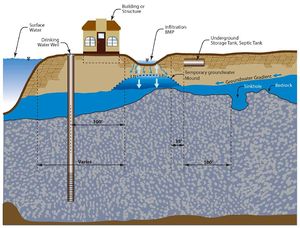
If the swale is constructed as an infiltration practice, the following table summarizes horizontal and vertical setback distances for required and recommended minimum distances from an infiltration practice to an above-ground or underground structure. It will be necessary to consult local ordinances for further guidance on siting infiltration practices.
.
Required and recommended minimum vertical and horizontal separation distances. This represents the minimum distance from the infiltration practice to the structure of concern. If the structure is above-ground, the distance is measured from the edge of the BMP to the structure. If the structure is underground, the vertical separation distance represents the distance from the point of infiltration through the bottom of the system to the structure, while the horizontal separation (often called setback) distance is the shortest distance from the edge of the system to the structure.
Link to this table
| Structure | Distance (feet) | Requirement or recommendation | Note(s) | |
|---|---|---|---|---|
| Vertical | Saturated soil | 3 | Requirement1 | |
| Bedrock | 3 | Requirement1 | ||
| Horizontal | Public supply well | 100 for sensitive wells; 50 for others3 | Requirement | |
| Building/structure/property line2 | 10 | Recommended | ||
| Surface water | none unless local requirements exist | If nearby stream is impaired for chloride, see [4] | ||
| Septic system | 35 | Recommended | ||
| Contaminated soil/groundwater | No specific distance. Infiltration must not mobilize contaminants. | |||
| Slope | 200 | Recommended | from toe of slope >= 20% | |
| Karst | 1000 up-gradient 100 down-gradient | Requirement1 | active karst | |
1 Required under the Construction Stormwater General Permit
2 Minimum with slopes directed away from the building
3If treating an average of 10,000 gallons per day; otherwise separation distance is 300 feet
Depth to groundwater and bedrock
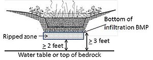
A separation distance of at least 3 feet is REQUIRED under the MPCA CGP between the bottom elevation of infiltration swales and the elevation of the seasonally high water table. Shallow bedrock areas should be avoided for dry swales with a minimum separation distance of 3 feet.
A field soil properties investigation is HIGHLY RECOMMENDED.
Karst topography
It is HIGHLY RECOMMENDED that infiltration practices not be used in active karst formations without adequate geotechnical testing.
Wellhead protection areas
See stormwater and wellhead protection for guidance and recommendations for determining the appropriateness of infiltrating stormwater in a Drinking Water Supply Management Area (DWSMA). For more information on source water protection see Minnesota Department of Health.
Soils hydrologic soil group mapping (see Design infiltration rates)
See NRCS Web Soil Survey for hydrologic soil descriptions for the swale location. A and B soils are potentially suitable for an infiltration swale. The maximum allowed field-measured infiltration rate shall not exceed 8.3 inches per hour for an infiltration swale.
Practice and site considerations
Several considerations are made in this section for the conceptual design of dry swales. Further design guidance and specifications are made in the following sections.
Conveyance
It is HIGHLY RECOMMENDED that the designer provides non-erosive flow velocities within the swale and at the outlet point to reduce downstream erosion. During the 10-year or 25-year storm (depending on local drainage criteria), discharge velocity should be kept below 4 feet per second for established grassed channels. Erosion control matting or rock should be specified if higher velocities are expected.
Pretreatment
If there is space for pretreatment prior to the swale it should be evaluated. Pretreatment should also be considered when runoff entering the swale has high concentrations of sediment. See the pretreatment section for more information.
Grading
- Slope of swale: The longitudinal slope of a dry swale may vary from 0.5 and 2 percent and will affect the selection of swale type. It is HIGHLY RECOMMENDED that the design engineer also considers the expected watershed flow to be conveyed by the swale in making this preliminary determination of design alternate.
- Swale bottom: It is HIGHLY RECOMMENDED that the swale bottom be no less than 3 feet wide and will be sized with the relative stage-dependent flow driven cross-sectional area in mind.
- Side slopes: It is RECOMMENDED that the maximum side slopes within a swale do not exceed 3H:1V and will be designed with the relative stage-dependent flow driven cross-sectional area in mind.
- Swale depth: Swale depth will be estimated based on the relative stage-dependent flow driven cross-sectional area.
- Infiltration and filtration considerations: The design engineer should review the results of the feasibility check to assist in the selection of swale type. An additional consideration includes watershed soil transport to the site. Watersheds with unstable soils or lack of vegetative cover (e.g., construction, farmland and highly impervious surfaces) can generate and transport excessive sediments to the swale that may affect both infiltration and filtration capacity. In these situations, pretreatment via sedimentation processes is HIGHLY RECOMMENDED. Another consideration is the level of compaction and structure of in-situ soils, when considering dry swales. Construction of developments and roads, for example, significantly alter the parent state of native soils and therefore their hydrologic soil classification should be downgraded for feasibility study purposes.

