Sediment control practices - Diversion barrier controls (cofferdams/temporary dikes)
This page is under development. We anticipate completion in autumn, 2016.
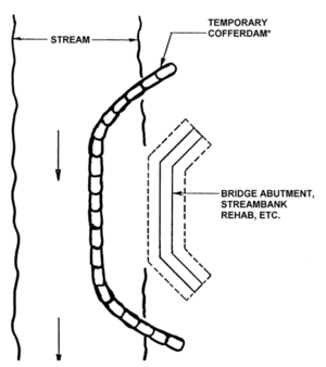
Cofferdams and small dikes are temporary barriers or dams used to stop or redirect the flow of water from a construction site work area, such as a support column foundation, a shoreline retaining wall location, a trench crossing at a stream or river, or other area adjacent to or within a body of water.
Contents
Purpose and function
Temporary diversion barrier controls (e.g. cofferdams) allow for “working in the dry” when construction projects are adjacent to or within surface waters. They prevent water from entering work zones on or near waterbodies, such as where excavation, concrete pouring, drilling, or other tasks are being conducted. They function by holding back water and creating a relatively dry area for construction activities requiring such conditions. These activities can include water exclusion enclosures adjacent to banks, within a river or lake, or water exclusion areas along stream reaches that have been dewatered by damming the upstream channel and creating a bypass ditch or pipe to deliver the diverted flow downstream beyond the work area (e.g., pipe trench location). Diversion barrier controls also prevent work zone sediment from entering the waterbody.
Applicability
Diversion barrier controls are appropriate for work zones that require dewatering and water exclusion during the construction period. Cofferdams and temporary dikes are almost always removed after work is completed. Floating sediment curtains may be used during the installation or use of diversion barrier controls to minimize turbid conditions in the waterbody.
Site applicability
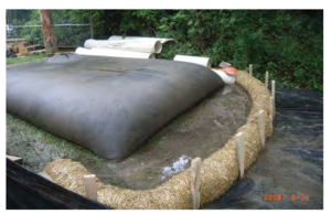
Temporary diversion barrier controls such as cofferdams and smaller dikes or barriers are very site specific. The type and configuration of the barrier is driven by the height and resulting pressure of water to be excluded, underwater conditions (i.e., soil, rock, etc.), the length of the barrier, the length of time and season of use, and other criteria. They provide a means to complete work required for underwater locations where temporary dewatering and water exclusion can be accomplished. Sheet pile cofferdams are often used for larger projects, such as bridge piers. Smaller, easily constructed barriers made of wood, earthen berms, Jersey wall sections, water-filled tubes, sandbags, and other materials can be used for smaller projects. Portable fabric dams can also be used to exclude water while preventing downstream siltation from eroding earthen dams.
Permit applicability
Section IV.C.1 of the 2013 MPCA Construction Stormwater General Permit states that “(t)he Permittee(s) must employ sediment control practices as necessary to minimize sediment from entering surface waters.” Diversion barrier controls keep water out of the work zone, and sediment out of the waterbody. Where diversions are used at work zones below the waterline, Section IV.C.2 of the permit states that “a floating silt curtain can be used as a perimeter control practice if the floating silt curtain is installed as close to shore as possible.” Floating silt curtains should be kept as close to the work zone as possible, to prevent turbid conditions at locations away from the work zone.
Effectiveness
Properly designed and installed cofferdams and other barriers are effective at keeping sediment out of the adjacent waterbody (see table below). Where cofferdams and temporary drainage ditches/channels are used to dewater or divert a stream, river, lake, or other area, special attention is required to ensure that bare soil along the bypass ditch or channel is stabilized. Methods can include lining a small temporary stream bypass channel with plastic, where necessary, or using geotextile to cover exposed bare areas. Careful installation and removal of the barrier and restoration of the work area is required to ensure effectiveness.
Expected performance for temporary diversion barrier controls
Link to this table
| Water Quantity | |
|---|---|
| Flow attenuation | Little or no design benefit |
| Runoff volume reduction | Little or no design benefit |
| Water Quantity | |
| Pollution prevention | |
| Soil erosion | Little or no design benefit |
| Sediment control | Primary design benefit |
| Nutrient loading | Secondary design benefit |
| Pollutant removal | |
| Total suspended solids | Primary design benefit |
| Total phosphorus | Secondary design benefit |
| Heavy metals | Secondary design benefit |
| Floatables | Little or no design benefit |
| Oil and grease | Little or no design benefit |
Planning considerations
Temporary diversion barrier control location is typically driven by engineering and operational staging considerations for the overall project (e.g., location of bridge support piers, lakeside armoring, sewer line route, etc.). Whenever possible, install and use temporary barriers during periods of low flow and warmer weather for greater efficiency and effectiveness. Winter and early spring may pose a greater risk of damage to diversions due to ice pressure and ice breakup. Components and materials are selected based on water height/hydraulic pressure, site conditions, longevity requirements, and other relevant factors. Temporary diversion barrier controls should be sited, constructed, and operated so as to cause minimal disruption to the aquatic environment, especially during fish spawning. Note that these projects usually need state, federal, or local permits. For example, placement of cofferdams in regulated waterbodies requires permit coverage from the US Army Corps of Engineers under Section 404 of the Clean Water Act, and a Water Quality Certification from MPCA.
Design and construction
Small barriers (i.e., less than 2-3 feet high) can be installed by field personnel based on standard designs and industry practice. Larger barriers require site specific engineering analysis. Design parameters for cofferdams and other water exclusion barriers incorporate the planning considerations noted above, along with safety concerns regarding stability, the power of flowing water at stream and river locations, and other water related safety issues. Other design considerations include the following:
- Mobilization areas for temporary diversion barrier placement or construction should be kept as small as possible to facilitate erosion and sediment control, and protected with downgradient sediment barriers.
- Placement activities should minimize vegetation removal and disturbance of adjacent areas to the maximum extent practicable.
- Where possible, use barrier controls constructed without earth fill – such as sand bags, sand totes, Jersey wall sections, collapsible fabric membrane dams, Aqua-Barrier®, Portadam, water filled bags/tubes, sheet piling, plastic wrapped hay bales/soil/aggregate/riprap, plastic sealed plywood, plastic sealed trench box lids, or other suitable materials.
- Earth fill barriers require stabilization to prevent erosion as bare soils come into contact with flowing water. Stabilization can often be achieved by covering bare areas with well-secured plastic sheeting.
- Sheet pile or collapsible fabric dams should be considered in sensitive areas, such as spawning areas.
- Ensure that barriers structures are of sufficient height to prevent waves or overflows from flooding the enclosed work area.
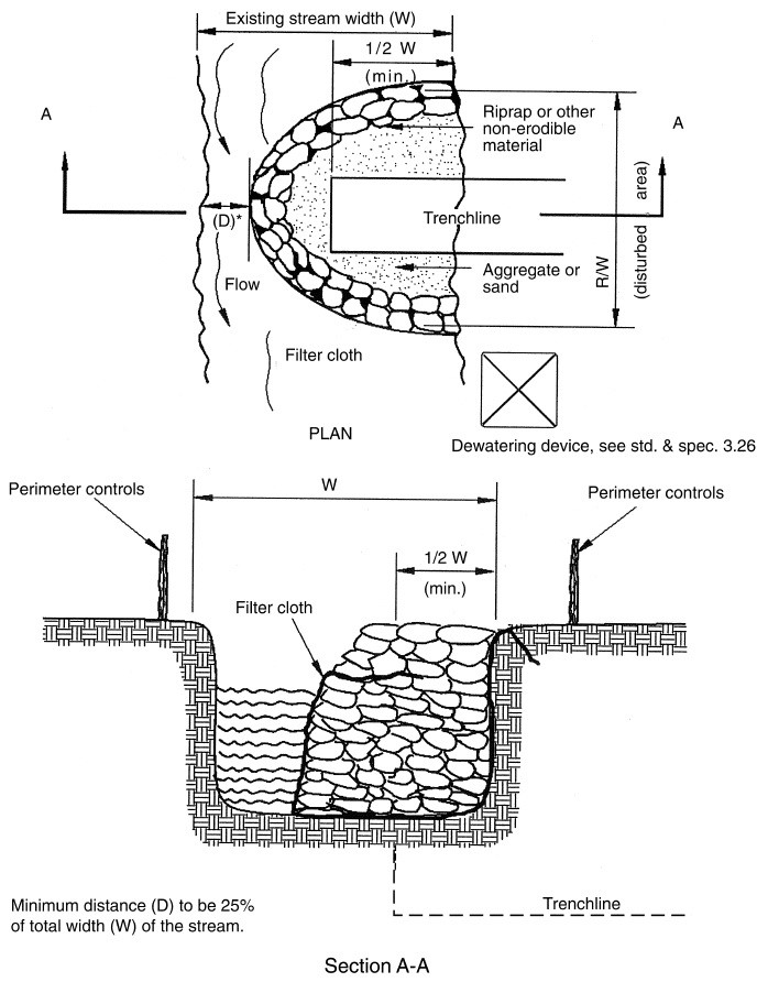
- For dewatering a stream reach, install barriers at upstream and downstream locations. If used, stabilize the bypass trench/channel with plastic sheeting, rock, or other liner material to prevent turbidity downstream.
- Dewatering of the enclosure typically requires sediment removal to ensure that turbid water is not discharged into nearby waterbodies. Prior to discharge to a water of the State, sediment-laden water is required to be treated with an appropriate BMP such as:
- Sand filters
- Flocculants
- Portable treatment unit
- Sediment pond or bags
- If stored onsite, material excavated from the mobilization site, the enclosure, or removed from the discharge water should be placed in stockpiles protected with erosion and sediment control measures, such as plastic sheeting or tarpaulin covers, downgradient sediment barriers, temporary mulch and seed, or other measures.
- Upon completion of work in the barrier area, demobilization and backfilling should occur with minimal additional soil disturbance and in a manner that minimizes turbidity in the nearby waterbody. Backfilling with hydraulic dredge or via slurry application should be avoided if possible.
- Suggested materials for temporary barriers in shallow water (up to 3 feet) include:
- Sandbags
- Plywood barriers
- Median barriers
- Jersey wall sections
- Water-filled bags or tubes (aqua tubes)
- Collapsible portable fabric membrane
- For temporary barriers in medium depth water (3 to 6 feet), suggested materials include:
- Large sand totes
- Collapsible portable fabric membrane
- Porta-dam
- Riprap with weighted silt curtain or plastic barrier
- For temporary barriers in deep water (more than 6 feet), suggested materials include:
- Sheet piling
- Other structural steel or concrete materials
Standards and Specifications
Detailed guidance on planning and executing projects within and adjacent to waterbodies can be found in Chapter 3 of the Minnesota DNR’s Best Practices Manual: Best Practices for Meeting DNR General Public Waters Work Permit GP 2004-0001 – Methods for In-Water Construction
In addition, MnDOT Specification 2451.3.A.3.a (Cofferdams; page 282) provides guidance for cofferdam placement and removal. The 2016 edition of MnDOT Standard Specifications for Construction can be found on page 282 of the following guidance document:
Inspection and maintenance
Due to the proximity to regulated waters, temporary diversion barriers require continuous observation and inspection throughout mobilization, installation, and deconstruction to ensure minimal impacts on nearby waterbodies. Key inspection guidance includes the following:
- Ensure that disturbed areas where mobilization and barrier installation occurs are protected with erosion prevention and sediment control measures. Inspect them weekly to ensure performance.
- Waters adjacent to the barrier structures should be inspected for turbidity on a continuous basis. Excessive turbidity should be addressed and eliminated to the extent possible. If the source of turbidity cannot be eliminated or mitigated, the use of floating turbidity curtains or other barrier is recommended.
- Dewatering intakes, transmission pipes/hoses, discharge areas, and treatment facilities for the discharge also require continuous monitoring and inspection to ensure that intake filters (if used) are serviced, pipes/hoses do not leak and discharge turbid water, and treatment facilities (e.g., filter bag, sediment trap/basin, etc.) are functioning properly.
Maintenance for temporary diversion barriers includes responding to the inspection and monitoring findings listed in the preceding subsection. Particular concerns include turbidity in the adjacent waterbody, erosion and sediment runoff from staging/mobilization areas, and performance of the BMP(s) responsible for sediment removal at the dewatering discharge location. In general, find and eliminate sources of turbidity, or use floating silt curtains to prevent turbid waters from migrating away from the immediate construction area. Clear sediment and debris from dewatering pump intake screens and filters as needed. Clean discharge area filters (e.g., filter fabric, silt fencing, etc.) and remove accumulated sediment before it restricts or consumes half of the effective treatment volume or storage capacity. Replace or clean filter bags as needed.
The following provides an example inspection and maintenance checklist (Source: Toronto and Region Conservation Authority)
- Ensure that the cofferdam or barrier is effectively isolating the work area.
- Ensure that an impermeable liner has been used in the construction of the barrier.
- Check for any leaks, particularly at the bottom and sides (streambanks) of the dam.
- Construction practices should prevent tearing of sand bags and release of material into the stream.
- Leaks should be addressed by constructing a second barrier to contain the leak.
Costs
The following table summarizes estimated BMP costs based on MnDOT data summarizing average bid prices for awarded projects in 2014.
Average bid prices for Specification Year 2014. Source: MnDOT
Link to this table
| Bid Item | Item Description | Units1 | Average Price |
|---|---|---|---|
| 2105.601/00045 | Temporary Stream Diversion System | LS | $26,292.50 |
| 2452.601/00011 | Steel Sheet Piling (Temporary) | LS | $107,614.29 |
| 2452.618/00011 | Steel Sheet Piling (Temporary) | SF | $16.75 |
| 2573.504/00010 | Sandbag Barrier | SF | $10.55 |
| 2105.601/00010 | Dewatering | LS | $65,587.94 |
1LS = lump sum; SF = square foot
Reference materials
Except where more stringent requirements are presented in this guidance, cofferdams (temporary dikes) shall comply with MnDOT and other state requirements. Primary design references include:
- MnDOT Erosion Control Handbook II
- 2013 Minnesota NPDES/SDS Construction Stormwater General Permit
- MnDOT Standard Specifications for Construction (2016 Edition)
- MnDNR Best Practices Manual: Best Practices for Meeting DNR General Public Waters Work Permit GP 2004-0001 Methods for In-Water Construction, Chapter 3
The following is a list of additional resources that are not specific to Minnesota:
- Delaware Erosion & Sediment Control Handbook (Cofferdam Stream Diversion)
- Illinois Urban Manual Practice Standard: Cofferdam (Code 803)
- Idaho Transportation Department (ITD) Temporary and Construction Site Best Management Practices (EC-3 Coffer Dam)
- Washington State Department of Transportation (WSDOT) Road Maintenance Guidelines, Part 2: Best Management Practices (Cofferdam)


