Guidance on calculating volumes for underground infiltration BMPs in the MIDS calculator
This page is in development and will contain guidance on calculating volumes for underground infiltration practices in the MIDS calculator
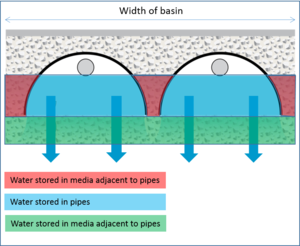
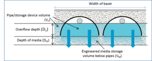
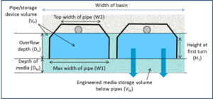
The Minimal Impact Design Standards calculator requires a user to input a value for water stored in an underground infiltration practice below the outflow (overflow) pipe and above the top of the underlying soil or engineered media. This is not a straightforward calculation because there are a wide variety of underground pipe shapes and because two different calculations must be made - one for storage in the pipe and another for storage in the media surrounding the pipe. If engineered media is used in the practice, the calculator also requires a calculation of the surface area of the engineered media. This calculation is fairly simple. Both these calculations can be made using a spreadsheet developed for this purpose. Water storage in an underground system is shown in the schematic to the right.
Calculating underground pipe storage volume (VP)
To calculate underground pipe storage volume (VP we need to add the volume stored in the pipes and in the media adjacent to and beneath the pipes.
Circular pipes
Considering the schematic to the right, the volume of water stored in the open space within the pipes (Vpipes) is given by
\( ((π r^2 * arccos((0.5 * D_p - D_O)/(0.5 * D_p))) - (((0.5 * D_p) - D_O) * sqrt((2 * 0.5 * D_p * D_O) - D_O * D_O))) * L_P * N_p \)
where
- r is the radius of the pipes (ft);
- Dp is the diameter of the pipes (ft);
- DO is the overflow depth (ft);
- Lp is the length of the pipes (ft); and
- Np is the number of pipes.
The above equation assumes a half-pipe configuration. The term on the right accounts for the volume above the bottom of the overflow. This water is assumed to discharge through the overflow and not vertically below the outflow.
The total volume of pipe and media (Vt) that can hold water is given by
\( (D_O + D_M) * L_B * W_B \)
where
- DM is the depth of media below the pipes (ft);
- LB is the length of the underground basin (ft); and
- WB is the width of the underground basin (ft).
The volume of the media (VM) equals the difference between the total volume and the volume in the pipes (Vt - Vpipes, in cubic feet. The volume of water stored in the media is equal to VM times the porosity. The Excel spreadsheet calculates the amount of water stored in media below the pipes and in media adjacent to the pipes, but this differentiation is not needed if the porosity of all media is the same.


