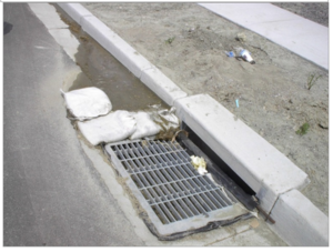
Sediment control practices - Storm drain inlet protection
Inlet protection is part of a system of sediment control devices and works best when upslope sources of sediment are reduced. For information on controlling upslope sources of sediment, see the following.
Contents
Purpose and function
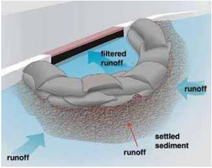
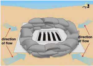
Inlet protection devices intercept and/or filter sediment before it can be transported from a site into the storm drain system and discharged into a lake, river, stream, wetland, or other waterbody. These devices also keep sediment from filling or clogging storm drain pipes, ditches, and downgradient sediment traps or ponds. Inlet protection may also include placement of a barrier to create a bypass of an inlet transferring flow downstream to a sediment trap, basin, or other inlet discharging to a non-critical area.
Applicability
Inlet protection devices may be applied to any curb inlet, drop inlet, manhole, catch basin, or other entry point to the stormwater drainage system that might receive inflows with high sediment levels. Inlet protection is critical because it often is the last treatment measure before stormwater enters receiving waters.
Site applicability
Construction sites often drain toward the inlets, pipes, and ditches that comprise the stormwater drainage system. Inlet protection devices can help protect these surface and subsurface systems from high levels of sediment in runoff. Inlet protection in areas with only surface drainage ditches are usually protected by stabilization practices, perimeter controls, and sediment traps. Consider the following when evaluating the use of inlet protection for a site.
- Most inlet protection devices are suitable for a drainage area of one acre or less. Runoff from larger disturbed areas should be routed to more suitable BMPs such as a temporary sediment trap or temporary sediment basin.
- Inlet protection devices may result in ponding of water around the inlet. This may result in a traffic hazard depending on site location.
- Inlet protection should be located in areas where potential ponding will not have adverse impacts.
- Under high flow conditions, sediment removal may be ineffective.
- Inlet protection is intended for low flows having relatively low sediment loading.
- Inlet protection that is not properly installed, maintained, or removed may result in short-circuiting of flow and introduction of sediment into the storm drain system.
- Stabilizing bare soil areas draining to the inlet and maintaining perimeter controls (e.g., silt fence, fiber logs) can help to prevent sediment overloads at inlet locations.
Permit applicability
Section IV.C.1 of the 2013 MPCA Construction Stormwater General Permit states that the permittee(s) “must employ Sediment control practices as necessary to minimize sediment from entering surface waters, including curb and gutter systems and storm sewer inlets.” In addition, Section IV.C.4 stipulates that “(a)ll storm drain inlets must be protected by appropriate BMPs during construction until all sources with potential for discharging to the inlet have been stabilized. Inlet protection may be removed for a particular inlet if a specific safety concern (street flooding/freezing) has been identified by the Permittee(s) or the jurisdictional authority (e.g., city/county/township/MnDOT engineer). The Permittee(s) must document the need for removal in the SWPPP.”
Where permanent stormwater controls include filtration systems, Section III.D.1.d of the 2013 MPCA Construction Stormwater General Permit specifies that “(t)o prevent clogging of the infiltration or filtration system, the Permittee(s) must use a pretreatment device such as a vegetated filter strip, small sedimentation basin, or water quality inlet (e.g., grit chamber) to settle particulates before the stormwater discharges into the infiltration or filtration system.”
Effectiveness
Properly selected, installed, and maintained inlet protection devices can remove 25 to 35 percent of total solids and 15 to 25 percent of nutrients from incoming flows (Florida DOT, 2010). They work very well in keeping sandy and some silty soils out of storm drains, but have somewhat limited effectiveness with fine clay soils passing through the barrier. Supplementing downgradient inlet protection devices with upgradient soil stabilization and perimeter controls increases in importance as site soils become finer (e.g. clays). Filter fabric can be added to inlet protection devices using coarse stone or aggregate to enhance sediment removal. However, the possibility of increased ponding should be considered. The following table summarizes expected performance for an array of typical water quantity and quality target constituents for storm drain inlet protection BMPs that are properly designed, installed, and maintained.
Expected performance for storm drain inlet protection
Link to this table
| Water Quantity | |
|---|---|
| Flow attenuation | Little or no design benefit |
| Runoff volume reduction | Little or no design benefit |
| Water Quantity | |
| Pollution prevention | |
| Soil erosion | Little or no design benefit |
| Sediment control | Primary design benefit |
| Nutrient loading | Secondary design benefit |
| Pollutant removal | |
| Total suspended solids | Primary design benefit |
| Total phosphorus | Secondary design benefit |
| Heavy metals | Secondary design benefit |
| Floatables | Little or no design benefit |
| Oil and grease | Little or no design benefit |
Planning considerations
Install inlet protection devices prior to upslope soil disturbance occurs. In newly developed areas, inlet protection should be installed immediately after the storm sewer inlets are installed. It is critical that the storm sewer inlet not be completely blocked by inlet protection when public safety is a concern. Inlet protection should only be used in locations where sediment can be removed and temporary ponding will not create a public safety hazard or cause property damage. Blocking an inlet can cause streets to flood and sediment to build up. Select inlet protection devices that do not pond water where adjacent areas are open to traffic. Examples of these include low-profile filter berms and filters suspended in the inlet structure. Because inlet protection devices are high-maintenance BMPs, ensure that up-gradient soil stabilization, perimeter protection, and other erosion control practices are in place to minimize the amount of sediment in stormwater flowing to inlets.
Design
Performance of all types of inlet protection depends on proper installation and use of materials. Materials should be checked for conformance with applicable MnDOT specifications. Inlet protection devices can be fabricated from clean aggregate, filter fabric, or other materials, or an appropriate device can be selected from the many commercial products available for construction site stormwater management. As noted above, devices that are bulky (e.g., concrete block) or that result in deeply ponded water and sediment deposits (e.g., rock and other berms) may not be appropriate for inlets on or immediately adjacent to public roadways.
Inlet protection can include
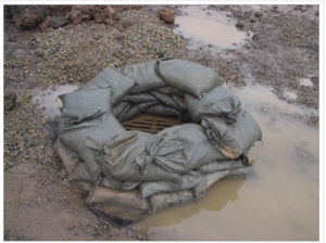
- rock berms, bags, tubes, and logs,
- compost and fiber logs,
- sediment dikes,
- inlet frame filters,
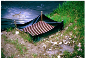
- silt fence enclosures,
- silt fence ring and rock filter (berm or log) combination,
- pop-up head risers,
- geotextile wraps,
- filter bag inserts, and
- other manufactured products such as drop inlet baskets.
MnDOT classifies protection devices for field inlets, curb inlets, curb inlets without a curb head, and culvert inlets. When using manufactured inlet protection products, the MnDOT approved/qualified products list should be consulted to determine the acceptable materials and products to protect each type of inlet. The current list of approved/qualified products for inlet protection can be found on the MnDOT website.
Regardless of the type of inlet protection BMP selected, there are a few key design guidelines.
- For best results, reduce demands on inlet BMPs through prompt stabilization of upslope areas and maintenance of appropriate perimeter controls downslope of disturbed areas.
- Filtration devices generally offer better performance than ponding devices, but they involve higher attention to maintenance – removing and cleaning them regularly.
- Inlet protection devices must intercept all incoming flows before they can enter storm drains.
- Select and install BMPs that cannot be floated or otherwise pushed away by heavy inflows.
- While overflow allowances are necessary to facilitate ponding and settling, no bypasses around the sides of the inlet protection device or below the device should occur unless the inlet is being intentionally bypassed (i.e. to prevent flows to a critical area by routing them to a sediment trap, basin, or non-critical area).
- Inlet protection BMPs should be left in place until the drainage area is stabilized with established vegetation or pavement.
Standards and specifications
MnDOT Standard Plan 5-297.405 provides standard detail for storm drain inlet protection (effective date: 8/6/2014). Specific BMP types covered include “Filter Bag Insert”, “Rock Log/Compost Log”, “Pop-Up Head”, “Sediment Control Inlet Hat”, and “Silt Fence Ring and Rock Filter Berm”.
MnDOT Specification 2573.3.M (Storm Drain Inlet Protection) provides general guidance for implementation and maintenance of inlet protection BMPs. Specifications 3137 (Coarse Aggregate) and 3886 (Silt Fence) may also be applicable depending on the selected design. See the 2016 edition of the MnDOT Standard Specifications for Construction (page 494.)
Inspection and maintenance
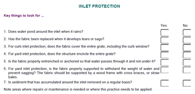
Storm drain inlet protection is only as effective as the filter or barrier used around the inlet. Properly maintaining inlet protection is difficult and often inlets become clogged, causing erosion elsewhere. A typical inspection should include the following bulleted list. An example inspection form is illustrated on the right.
- Inspect inlet protection immediately before and after rain events and snowmelt.
- Note where no inlet protection is present, and determine need for inlet protection.
- Look for and document sediment deposits on the pavement and sediment on inlet filters.
- During cold weather, note if ice and snow are affecting performance.
- Note any actual or potential bypasses around the sides or underneath inlet protection.
- Ensure that there are no large holes or gaps in the inlet protection.
- Assess whether or not the BMP will be dislodged in the event of high incoming flows.
- Note where overflows occur during heavy rain, to ensure public safety and erosion control
- Observe and document any safety concerns regarding sediment deposits and the BMP, such as mud in the roadway (especially high-speed roads), BMP components in traffic lanes, etc.
Inlet protection devices are high-maintenance BMPs, and typically require maintenance after nearly every precipitation event. Typical maintenance activities are summarized below.
- Maintain inlet BMPs until all upslope areas are stabilized, and incoming flows are clean.
- Remove sediment deposits on the pavement before they reach halfway up to the overflow point.
- Remove sediment deposits immediately if they might affect traffic safety.
- Remove sediment from filtration areas, and clean filter surfaces to ensure future performance.
- Geotextiles, rock, and perforated pipe can easily become plugged with sediment. These should be routinely cleaned and/or replaced.
- Any excavated sediment should be placed where it will not create an erosion problem.
- Remove snow and ice affecting performance – use hand tools or heat; do not use salt.
- Repair or otherwise address bypasses over, underneath, or around the sides of the BMP.
- Ensure that heavy rains overtopping the BMP do not cause safety or erosion concerns.
- Repair any holes or gaps in the inlet protection device.
- If flows are dislodging the BMP, use sand/rock bags or other item to hold the BMP securely in place, or replace the failing BMP with another device that can handle incoming flows.
- Where inlet BMPs might impact traffic safety, select a low-profile alternative or use filter inserts.
- If inlet protection devices cannot be used due to traffic safety concerns, the sediment levels in incoming flows must be reduced through immediate stabilization of upslope bare areas and enhanced perimeter controls. If the unprotected inlet discharges to a suitable area, a sediment trap may be installed to address the untreated flow.
The following table summarizes MnDOT’s workmanship and rework schedule (2016; version under development at the time of manual update). The table identifies common deficiencies for various types of temporary sediment control BMPs, including storm drain inlet protection, and corrective actions for these deficiencies. Once complete, the full, final version of this table will replace Table 2573-1 in MnDOT Standard Specifications for Construction (2016 edition).
Temporary sediment control: corrective actions
Link to this table
| Item | Corrective Action Required if | Corrective Action1 |
|---|---|---|
| Storm drain inlet protection |
|
|
1The number corresponds with the same number in the column "Corrective Action Required"
Costs
The following table summarizes estimated BMP costs based on MnDOT data summarizing average bid prices for awarded projects in 2014.
Average Bid Prices Storm drain for spec year 2014
Link to this table
| Bid item | Item description | Units | Average price |
|---|---|---|---|
| 2573.530/0010 | Storm drain inlet protection | Each | $175.21 |
| 2573.531/0010 | Storm drain inlet protection | Lump sum | $500.00 |
Reference materials
Except where more stringent requirements are presented in this guidance, BMPs shall comply with MnDOT and other state requirements. Primary design references include:
- MnDOT Erosion Control Handbook II
- Minnesota Urban Small Sites Best Management Practice Manual (Inlet Protection)
- 2013 Minnesota NPDES/SDS Construction Stormwater General Permit
- MnDOT Standard Specifications for Construction (2016 Edition)
- MnDOT Standard Drawings for use in Construction Plans
The following is a list of additional resources that are not specific to Minnesota:
- Clark County Washington Stormwater Manual (BMP C220: Storm Drain Inlet Protection)
- Clean Water Services Erosion Prevention and Sediment Control Manual (4.3.5 Inlet Protection)
- Florida DOT 2010 study on Inlet Protection Devices and their Effectiveness, conducted by the University of Central Florida’s Civil, Environmental, and Construction Engineering Department
- Ohio Environmental Protection Agency (Ohio EPA) Construction Site Inspection Checklist for OHC000004
- North Carolina Erosion and Sediment Control Planning and Design Manual (6.50-6.55 Inlet Protection)
- Tennessee Department of Environment and Conservation (TDEC) Erosion and Sediment Control Handbook (7.35 Inlet Protection)
- Virginia Erosion and Sediment Control Handbook (3.07 Storm Drain Inlet Protection)
Related pages
- Stabilization practices
- Erosion prevention practices - temporary seeding and stabilization
- Erosion prevention practices - natural and synthetic mulches
- Erosion prevention practices - tackifiers and soil stabilizers
- Erosion prevention practices - erosion control blankets and anchoring devices
- Erosion prevention practices - turf reinforcement mats
- Sediment control practices
- Sediment control practices - Vehicle tracking BMPs
- Sediment control practices - Perimeter controls for disturbed areas
- Sediment control practices - Check dams (ditch checks, ditch dikes)
- Sediment control practices - Diversion barrier controls (cofferdams/temporary dikes)
- Sediment control practices - Storm drain inlet protection
- Sediment control practices - Outlet energy dissipation
- General principles for erosion prevention and sediment control at construction sites in Minnesota
- Construction stormwater photo gallery
