Linear Permanent Stormwater Management Design Flow Chart


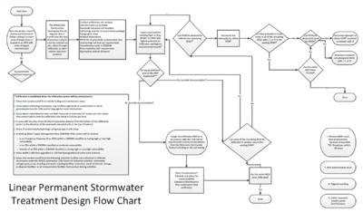
The flow chart is set up for SWPPP designers to identify several areas for Best Management Practices (BMPs) during the planning phase and take each one individually through the decision process. This is also meant to assist with the majority of linear projects, and there may be certain instances where this flow chart will not work (e.g. when opportunities exist to infiltrate off site runoff, the use of other volume reduction practices, when opportunities to treat off site runoff through filtration or wet sedimentation basins, if other treatment methods are being used, etc.). If that is the case, it may be best to contact the Minnesota Pollution Control (MPCA) Stormwater Hotline at 651-757-2119.
1: The preliminary site analysis should use: All available soils information (existing soil borings, web soil survey maps, NRCS soil maps, etc.), wetland maps (NWI or equivalent), recommended setback distances in the Minnesota Stormwater Manual, local zoning requirements that could include required setback distances for infiltration practices, EIS/EAW commitments must be included as required in the National Pollutant Discharge Elimination System/State Disposal System (NPDES/SDS) Construction Stormwater (CSW) permit, permitted Municipal Separate Storm Sewer Systems (MS4s) could require more volume reduction or water quality treatment than State requirements.
The goal of the preliminary site analysis is to get enough information to move to the next step and target several potential infiltration areas within existing Right of Way (ROW) when possible or by acquiring additional ROW when necessary to meet the volume reduction requirements of the CSW permit.
2: It is highly recommended that permittees identify as many potential infiltration areas as possible. The characteristics of these areas will be soils with good infiltration characteristics (HSG A, B, or C), adequate separation to seasonally saturated soils (>3’), areas that will receive discharges from impervious surface on the project, and avoidance of areas of steep slopes (>20%). This gives more flexibility to make changes to the design if prohibitions are discovered, and gives the highest probability of infiltrating the Water Quality Volume (WQV) in the existing ROW. Areas to target to increase environmental benefit could include discharge points from the project (especially discharging to surface waters, highest preference given to special or impaired waters). Appropriate testing should include soil borings or test pits that have a soil texture analysis and specifically identify depth to seasonally saturated soils (Note: current groundwater depth is not usually the seasonally saturated soil elevation. This often needs to be requested in a soil boring and analyzed by a soil scientist). Testing must be done in the approximate BMP location to ensure accurate results.
3: Examples of documentation could include: Results of soil borings, test pits, infiltrometer tests or any other test to determine infiltration rates, maps or geotechnical information identifying karst areas or Drinking Water Supply Management Area (DWSMA). The documentation will either be used to show prohibitions exist, or be used to show the system complies with the design requirements in the NPDES/SDS CSW permit.
4: Permittees must consider other forms of volume reduction if infiltration is prohibited. While this may not be common on linear projects, possible options could include cisterns or reuse from stormwater ponds.
5: At this stage, permittees should target acquiring ROW in areas that are most likely to provide infiltration, which could include expanding an area that was already identified as able to infiltrate. Use the information obtained in the preliminary site analysis to determine these areas.
6: Potential reasons why obtaining ROW may be infeasible: Land owners requesting more than fair market value, not required to condemn buildings, land owners unwilling to sell, etc. Typically, this step should be completed by the 30% planning phase of the project. All attempts to obtain ROW must be done during the planning phase and documented in the SWPPP.
7: Areas within the existing ROW should be prioritized based on the amount of impervious surfaces the BMP can treat and areas that will have the highest environmental benefit (near lakes, wetlands, streams, etc.).
8: At this stage, permittees should target acquiring ROW in areas that will have the highest environmental benefit. Areas could include bridge approaches and decks, stream crossings, or areas adjacent to lakes or wetlands.
9: Other considerations are items to ensure permit compliance after the design phase. It is required that infiltration areas be constructed only after the drainage area is stabilized unless there are rigorous BMPs in place to keep sediment laden runoff completely away from the BMP. It is important that this phasing plan is addressed in the SWPPP. It is also required that there is a maintenance plan, including who we be performing the maintenance. It also may be necessary to have a method to ensure that the BMP is functioning correctly such as visually verifying, testing with a double ring infiltrometer, etc. so the site can meet the Final Stabilization requirements in the NPDES/SDS CSW permit and submit a Notice of Termination (NOT).
Linear Permanent Stormwater Treatment Design Flow Chart Supplement
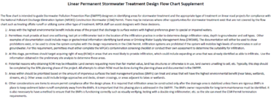
The flow chart is intended to guide Stormwater Pollution Prevention Plan (SWPPP) designers in identifying areas for stormwater treatment and the appropriate type of treatment on linear road projects for compliance with the National Pollutant Discharge Elimination System (NPDES) Construction Stormwater (CSW) Permit. There may be instances where other opportunities for stormwater treatment exist that are not covered by the flow chart such as treating offsite runoff or utilizing some other type of treatment. MPCA staff can assist designers with these decisions.
- Areas with the highest environmental benefit include areas of the project that discharge to surface waters with highest preference given to special or impaired waters.
- Permittees must provide at least one soil boring, test pit or infiltrometer test in the location of the infiltration practice in order to determine design infiltration rates, depth to groundwater and soil types. Other examples of documentation could include maps or geotechnical information identifying karst areas or Drinking Water Supply Management Area (DWSMA). The documentation will either be used to show prohibitions exist, or be used to show the system complies with the design requirements in the CSW Permit. Infiltration systems are prohibited if the system will mobilize high levels of contaminates in soil or groundwater. For this requirement, permittees must either complete the MPCA’s contamination screening checklist or conduct their own assessment to determine the suitability for infiltration.
- At this stage, permittees should target acquiring right of way (ROW) in areas that are most likely to provide infiltration, which could include expanding an area that was already identified as able to infiltrate. Use the information obtained in the preliminary site analysis to determine these areas.
- Potential reasons why obtaining ROW may be infeasible: Land owners requesting more than fair market value, land has structures or otherwise is in use, land owners unwilling to sell, etc. Typically, this step should be completed by the 30% planning phase of the project. All attempts to obtain ROW must be done during the planning phase and documented in the SWPPP.
- Areas within should be prioritized based on the amount of impervious surfaces the best management practices (BMPs) can treat and areas that will have the highest environmental benefit (near lakes, wetlands, streams, etc.). Other areas could include bridge approaches and decks, stream crossings, or areas adjacent to lakes or wetlands.
- Other considerations are items to ensure permit compliance after the design phase. It is required that infiltration areas be constructed only after the drainage area is stabilized unless there are rigorous BMPs in place to keep sediment laden runoff completely away from the BMPs. It is important that this phasing plan is addressed in the SWPPP. The BMPs owner responsible for long-term maintenance must be identified. It is also necessary to have a method to ensure that the BMPs is functioning correctly such as visually verifying, testing with a double ring infiltrometer, etc. so the site can meet the CSW Permit termination requirements.