Sediment control practices - Outlet energy dissipation
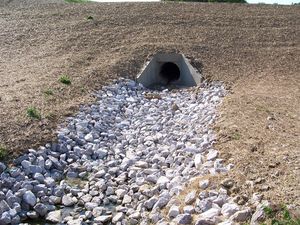
Permanent or temporary energy dissipators prevent erosion, turbulence, and turbidity where stormwater pipes or ditches discharge to unprotected areas, such as channel banks, slopes, or upslope outfall locations. Their main purpose is to reduce the speed of concentrated flows to prevent scour at conveyance outlets. This practice is also called Scour Protection or Outlet Protection. Common types of outlet protection devices include concrete aprons, riprap-lined basins, and settling basins.
Contents
Purpose and function
Energy dissipators intercept incoming flows from pipes and ditches to deflect, scatter, or otherwise neutralize the erosive force of concentrated, moving stormwater. These structures are intended to protect soil from turbulence and high velocities, which can otherwise cause scour erosion. They typically consist of a structural apron lining fabricated from riprap, concrete, turf reinforcement mats, or other structural materials. Certain types of basins (e.g., settling/stilling/impact basins) can also function as energy dissipators. Many of these techniques are effective and relatively inexpensive and easy to install. Energy dissipators require careful design based on the hydraulic forces of concentrated flows exiting pipes and ditches.
Applicability
Energy dissipators at pipe and ditch outlets are appropriate for any unpaved or otherwise non-armored location where concentrated flows are discharged to areas subject to erosion.
Site applicability
Energy dissipators are used where concentrated flows are discharged against channel banks, on poorly stabilized slopes, or onto upslope areas that are not protected against erosive flows. They are appropriate at the outlets of ponds, pipe slope drains, culverts, ditches, or other conveyances, and where runoff is conveyed to a natural or manmade drainage feature such as a stream, wetland, lake, or ditch. The most common applications include riprap aprons at culvert outlets, ditches lined with turf reinforcement matting, and stilling or impact basins designed to accept and dissipate high-energy stormwater flows. Some important considerations when selecting energy dissipators for a site include the following.
- It may be difficult to remove sediment trapped by the dissipator without removing and replacing the structure.
- Rock/riprap outlets with high velocity flows require frequent maintenance.
- These BMPs may not be aesthetically pleasing.
Permit applicability
The Construction Stormwater general permit has several requirements pertaining to sediment control practices.
- Permittees to provide energy dissipation for temporary basin outlets within 24 hours after connection to a surface water.
- Permittees must provide temporary or permanent energy dissipation at all pipe outlets within 24 hours after connection to a surface water or permanent stormwater treatment system.
- Where a temporary sediment basin meeting the requirements of item 14.3 through 14.9 is infeasible, permittees must install effective sediment controls such as smaller sediment basins and/or sediment traps, silt fences, vegetative buffer strips or any appropriate combination of measures as dictated by individual site conditions. In determining whether installing a sediment basin is infeasible, permittees must consider public safety and may consider factors such as site soils, slope, and available area on-site. Permittees must document this determination of infeasibility in the SWPPP.
- Permittees must provide energy dissipation for the basin outlet within 24 hours after connection to a surface water.
- Permittees must provide temporary or permanent energy dissipation at all pipe outlets within 24 hours after connection to a surface water or permanent stormwater treatment system.
- Permittees must design basin outlets to prevent short-circuiting and the discharge of floating debris.
Effectiveness
Properly installed temporary and permanent energy dissipators are effective in preventing channel bank scour, slope gullying, and plunge pool erosion where concentrated flows discharge into unarmored, poorly stabilized areas.
Expected performance for outlet energy dissipators
Link to this table
| Water Quantity | |
|---|---|
| Flow attenuation | Little or no design benefit |
| Runoff volume reduction | Little or no design benefit |
| Water Quantity | |
| Pollution prevention | |
| Soil erosion | Primary design benefit |
| Sediment control | Secondary design benefit |
| Nutrient loading | Little or no design benefit |
| Pollutant removal | |
| Total suspended solids | Secondary design benefit |
| Total phosphorus | Little or no design benefit |
| Heavy metals | Little or no design benefit |
| Floatables | Little or no design benefit |
| Oil and grease | Little or no design benefit |
Planning considerations
A review, analysis, and evaluation of both the location and magnitude of concentrated flows associated with culvert, ditches, and channel discharges can help identify where scour and other erosion are likely to occur. Culvert outlets are common places where energy dissipators are needed, as are locations where ditches discharge to terraces or slopes that are not armored against erosive, concentrated flows. In cases where flow velocities are too high for the economical use of an apron, a stilling basin or impact basin may be more appropriate. These structures dissipate energy from high-velocity flows to an acceptable level before discharging to an outlet channel.
Energy dissipator design and installation instructions can usually be included in the construction/installation plans for pipes, ditches, and channels. For example, culverts can be outfitted with outlet riprap aprons during installation, and ditches discharging into larger channels can be designed to include appropriate turf reinforcement matting and/or other structural elements where small, high-velocity ditches discharge against poorly armored banks of larger channels.
Key planning considerations for large projects – especially those involving mass clearing and grading – include 1) minimizing the number and magnitude of concentrated flows during initial clearing and grading, to the extent possible; and 2) installing permanent drainage features (e.g., stabilized ditches, channels, energy dissipators, vegetated channel buffers, etc.) as early as possible, especially since installing, stabilizing, and maintaining temporary drainage infrastructure is expensive and time-consuming. Following these two recommendations can reduce construction costs and increase the overall efficiency of sediment and erosion control on a site.
Due to their proximity to surface water locations, many energy dissipation practices are installed in areas subject to state, federal, or local permits. For example, where energy dissipation materials are installed within waters of the U.S., permit coverage from the U.S. Army Corps of Engineers under Section 404 of the Clean Water Act and water quality certification from MPCA under Section 401 of the Clean Water Act is required.
Design and construction
Temporary energy dissipators at construction sites, which often include riprap aprons, are designed for short-term (e.g., less than one year) erosion control during the construction period. Design of permanent dissipators will be driven by erosive force estimates and the final aesthetics desired at the dissipator location. For example, highway and industrial areas may be suitable sites for the use of riprap aprons or concrete structures at culvert outlets, while the softer look of vegetation growing through underlying turf reinforcement mats may be more appropriate for some commercial and residential areas. Temporary devices should be completely removed as soon as the surrounding drainage area has been stabilized.
In general, dissipator design focuses on a few key variables: flow velocity, flow depth, and culvert or ditch characteristics (e.g., type, size, shape, roughness), as well as approaches for spreading out the outlet flow, deflecting it via armored surfaces, absorbing its energy in a stilling or impact basin, or roughening flow paths to reduce erosive forces. A properly designed riprap apron employs several of these approaches including spreading the flow and deflecting and roughening its movement through the use of adequately sized rock. The subsections below provide summary design information and references for designing a variety of energy dissipators. Alternative methods for energy dissipation can be found in the Federal Highway Administration’s HEC-14 (see Reference Materials).
Riprap aprons
Most outlet protection applications consist of a structural apron lining. Apron linings can be made of riprap, concrete, grouted riprap or other structural materials. Riprap aprons are best suited for temporary use during construction, while grouted or wire tied rock riprap can decrease maintenance requirements. As indicated above, in some cases flow velocities may be too high for economical use of an apron.
Outlet energy dissipators may or may not require a detailed design, depending upon the scope and complexity of the job. For outlets with very high velocities or very low tailwater conditions, outlet protection should be designed only by a qualified engineer. The following criteria are recommended for the design of structurally lined aprons below pipe outlets.
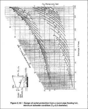
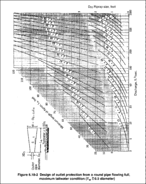
- The tailwater depth must be determined immediately downstream of the outlet pipe, and the maximum capacity of the pipe should be used when computing tailwater. If the tailwater elevation is less than the elevation halfway up on the pipe outlet, the outlet is classified as a minimum-tailwater-condition outlet. If the tailwater exceeds this level, the outlet is classified as a maximum-tailwater-condition outlet. Pipes that discharge onto broad, flat areas without a defined channel can usually be classified as a minimum-tailwater-condition outlet. Refer to the figures at the right for minimum and maximum tailwater conditions.
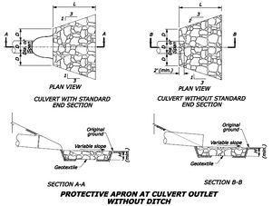
- The most desirable configuration for the outlet is a straight section. This is the only alignment that should be used for the ground design charts shown to the right. If a curve is necessary before the end of the apron, the curve should be located in the upper section of the apron, and a special design should be used. The dimensions of the apron should be determined from the appropriate table. Apron-length requirements are computed from the figures to the right, as applicable. The apron should be constructed level and at the elevation of the outlet pipe invert.
- The apron can be constructed of riprap, cable-tied concrete or other suitable material. If riprap is used, the median rock size (D50) can be determined from the example information in the table below; detailed design criteria can be derived from the figures to the right. A nonwoven geotextile blanket should be used under the apron if riprap is used.
- Outlets on slopes steeper than 10 percent should have additional protection, such as an engineered energy dissipator (e.g., chute blocks, paved or riprapped stilling basin, etc.).
Example sizing information for riprap energy dissipators at culvert outlets. Source: Kentucky Division of Water
Link to this table
| Culvert size | Avg. rock diameter | Apron width1 | Apron length2 | Apron length3 |
|---|---|---|---|---|
| 8" | 3" | 2–3 ft. | 3–5 ft. | 5–7 ft. |
| 12" | 5" | 3–4 ft | 4–6 ft. | 8–12 ft. |
| 18" | 8" | 4–6 ft. | 6–8 ft. | 12–18 ft. |
| 24" | 10" | 6–8 ft. | 8–12 ft. | 18–22 ft. |
| 30" | 12" | 8–10 ft. | 12–14 ft. | 22–28 ft. |
| 36" | 14" | 10–12 ft. | 14–16 ft. | 28–32 ft. |
| 42" | 16" | 12–14 ft. | 16–18 ft. | 32–38 ft. |
| 48" | 20" | 14–16 ft. | 18–25 ft. | 38–44 ft. |
1Apron width at the narrow end (pipe or channel outlet)
2Apron length for slow-flow (no pressure head) culverts
3Apron length for high flow (pressure head) culverts
Stilling basin/impact basin
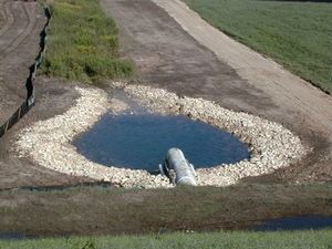
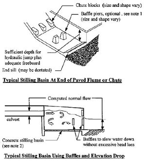
A stilling basin is an excavated pool of water that is lined with riprap and used to dissipate energy from high-velocity flow. An impact basin is a reinforced concrete structure that slows water velocities to an acceptable level before discharging water to an outlet channel. Riprap stilling basins and plunge pools reduce flow velocity rapidly. They should be considered as an alternative to riprap aprons where pipe outlets are cantilevered, or where high flows would require an excessive apron length. Where conditions warrant, other energy dissipators such as concrete impact basins may be considered.
Stilling basins are used to convert flows from supercritical to subcritical flow regimes by allowing a hydraulic jump to occur within the structure over a wide range of flow conditions and depths. A professional engineer must design energy dissipators and stilling basins using hydraulic computations. A primary operation and maintenance concern for both energy dissipators and stilling basins is the accumulation of sediment and trash.
Standards and specifications
MnDOT Standard Plates 3133D and 3134D provide standard detail for “Riprap at RCP Outlets” and “Riprap at CSP Outlets”], respectively (effective date: 8/6/2014).
The MnDOT Standard Specifications for Construction (2016 edition) Specification 2573.3.L (Culvert End Controls) states that culvert outlet ends must be protected with “energy dissipation devices, transition devices, or both to reduce erosion and sediment loss while reducing the velocity of water existing culvert.” Specifications 2501 (Pipe Culverts) and 2503 (Pipe Sewers) may also be applicable depending on the BMP/device chosen. Additional materials specifications that may be applicable include Specifications 2511 and 3601 (Riprap), and 3733 (Geotextile). The 2016 edition of the MnDOT Standard Specifications for Construction.
Inspection and maintenance
Inspect energy dissipators before periods of flow to ensure they are prepared to function. Inspect after flow periods (including stormwater runoff and runoff from snowmelt) to observe and document deficiencies. Inspection guidelines include the following.
- Confirm that the length, width, shape, and composition of the energy dissipator matches design criteria after construction and before/after flow events.
- After periods of flow, look for signs that dissipator components have been dislodged or moved.
- Inspect apron(s) for displacement of riprap and damage to underlying fabric.
- Observe and document any scour or other erosion in the vicinity of the energy dissipator.
- Note any accumulations of woody or other debris at the outlet or within the dissipator structure.
- Inspect culvert or ditch inlet and flow areas for accumulations of woody or other debris.
Energy dissipation devices should be inspected periodically to check for scour, and any needed repairs should be completed promptly to prevent further damage. Below are typical maintenance practices.
- Restore dissipator to its original specifications if it is found to diverge from design criteria.
- Replace rock or other components that have been dislodged by heavy flows.
- If rock continues to wash away, consider using larger material.
- Repair and damage to underlying fabric.
- Where erosion/scour is occurring outside dissipator area, increase dissipator size in the eroded area.
- Frequently remove sediment and other debris accumulations from inlets, flow pipes/ditches, and the dissipator area.
Costs
Below is an estimated BMP cost based on MnDOT data summarizing average bid prices for awarded projects in 2014.
- Bid item = 2573.530/0010
- Item Description = Culvert End Controls
- Average Price = $194.30 each
Reference materials
Except where more stringent requirements are presented in this guidance, BMPs shall comply with MnDOT and other state requirements. Primary design references include:
- MnDOT Erosion Control Handbook II
- 2018 Minnesota NPDES/SDS Construction Stormwater General Permit
- MnDOT Standard Specifications for Construction
- MnDOT Standard Plates (Approved Standard Drawings)
The following is a list of additional resources that are not specific to Minnesota:
- California Stormwater BMP Handbook (BMP EC-10: Velocity Dissipation Devices)
- Clark County Washington Stormwater Manual (BMP C209: Outlet Protection)
- Clean Water Services Erosion Prevention and Sediment Control Manual (4.2.4 Outlet Protection)
- Federal Highway Administration, Hydraulic Engineering Circular No. 14 (“HEC 14”), Third Edition – Hydraulic Design of Energy Dissipators for Culverts and Channels
- Kentucky Division of Water Best Management Practices (BMPs) for Controlling Erosion, Sediment, and Pollutant Runoff from Construction Sites – Planning and Technical Specifications Manual
- North Carolina Erosion and Sediment Control Planning and Design Manual (6.41 Outlet Stabilization Structure)
- Tennessee Department of Environment and Conservation (TDEC) Erosion and Sediment Control Handbook (7.23 Outlet protection)
- Virginia Erosion and Sediment Control Handbook (3.18 Outlet Protection)
Related pages
- Erosion prevention practices
- Erosion prevention practices - temporary seeding and stabilization
- Erosion prevention practices - natural and synthetic mulches
- Erosion prevention practices - tackifiers and soil stabilizers
- Erosion prevention practices - erosion control blankets and anchoring devices
- Erosion prevention practices - turf reinforcement mats
- Erosion prevention practices - Riprap
- Sediment control practices
- Sediment control practices - Vehicle tracking BMPs
- Sediment control practices - Perimeter controls for disturbed areas
- Sediment control practices - Check dams (ditch checks, ditch dikes)
- Sediment control practices - Diversion barrier controls (cofferdams/temporary dikes)
- Sediment control practices - Storm drain inlet protection
- Sediment control practices - Outlet energy dissipation
- Sediment control practices - Sediment traps and basins
- Sediment control practices - Stabilized earth/soil berm
- Construction stormwater treatment - dewatering, including chemical treatment and sediment filtration
- Construction stormwater best management practice – buffer zones
- Other practices
This page was last edited on 15 February 2023, at 12:08.

