Difference between revisions of "Calculating credits for permeable pavement"
m |
m |
||
| Line 1: | Line 1: | ||
<!--{{alert|The anticipated construction period for this page is January through March, 2013|alert-under-construction}}--> | <!--{{alert|The anticipated construction period for this page is January through March, 2013|alert-under-construction}}--> | ||
| + | |||
| + | {{alert|The MPCA has contracted with CDM Smith to develop [[Overview of stormwater credits|credit]] pages for most structural BMPs in the Manual. We anticipate these pages will be completed by June of 2014.|alert-under-construction}} | ||
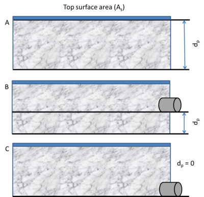
[[File:Design schematic 2.png|thumb|400px|alt=schematic illustrating dimensions used to calculate storage volume for permeable pavement. The volume equals the reservoir depth (d<sub>p</sub>) times the permeable pavement surface area. Design A shows a system with no underdrain in which d<sub>p</sub> equals the height of the reservoir layer. Design B shows an elevated underdrain, with d<sub>p</sub> equal to the distance from the bottom of the underdrain to the underlying soil. Design C shows an underdrain at the bottom.|<font size=3>Schematic illustrating dimensions used to calculate storage volume for permeable pavement. The volume equals the reservoir depth (d<sub>p</sub>) times the permeable pavement surface area. Design A shows a system with no underdrain in which d<sub>p</sub> equals the height of the reservoir layer. Design B shows an elevated underdrain, with d<sub>p</sub> equal to the distance from the bottom of the underdrain to the underlying soil. Design C shows an underdrain at the bottom.</font size>]] | [[File:Design schematic 2.png|thumb|400px|alt=schematic illustrating dimensions used to calculate storage volume for permeable pavement. The volume equals the reservoir depth (d<sub>p</sub>) times the permeable pavement surface area. Design A shows a system with no underdrain in which d<sub>p</sub> equals the height of the reservoir layer. Design B shows an elevated underdrain, with d<sub>p</sub> equal to the distance from the bottom of the underdrain to the underlying soil. Design C shows an underdrain at the bottom.|<font size=3>Schematic illustrating dimensions used to calculate storage volume for permeable pavement. The volume equals the reservoir depth (d<sub>p</sub>) times the permeable pavement surface area. Design A shows a system with no underdrain in which d<sub>p</sub> equals the height of the reservoir layer. Design B shows an elevated underdrain, with d<sub>p</sub> equal to the distance from the bottom of the underdrain to the underlying soil. Design C shows an underdrain at the bottom.</font size>]] | ||
Revision as of 13:53, 31 January 2014
The MPCA has contracted with CDM Smith to develop credit pages for most structural BMPs in the Manual. We anticipate these pages will be completed by June of 2014.
Permeable pavement is a tool that can achieve reductions in stormwater volume and pollutant loading. Permeable pavements allow stormwater runoff to filter through surface voids into an underlying stone reservoir for temporary storage and/or infiltration. Volume and pollutant reductions constitute stormwater credits that can be used to meet various goals (e.g. Total Maximum Daily loads (TMDLs), Minimal Impact Design Standards (MIDS) performance goals). Permeable pavement will achieve the greatest credit when it is properly designed, constructed and maintained.
Permeable pavement can be located anywhere in the treatment train. However, pretreatment that removes sediment from runoff draining onto permeable pavement from impervious surfaces is desirable since sediment can clog permeable pavements. For that reason, pretreatment areas should emit practically no sediment onto the permeable pavement surface. Locating such areas next to impervious surfaces upslope from the permeable pavement may not be possible on some sites. Permeable pavement can be considered a pre-treatment device and included in a stormwater treatment train if underdrains are utilized within the storage reservoir. The underdrains will typically be routed to a bioretention area.
- The permeable pavement is properly designed.
- The permeable pavement was properly constructed, consistent with the design criteria.
- The permeable pavement is properly maintained. The performance of the permeable pavement should be regularly assessed.
Assumptions used to calculate credits may also vary with each calculator or model. To calculate credits it is important to ensure that your calculation is consistent with the assumptions made in the model or calculator you are using. Detailed discussions of assumptions may be found in user's manuals or other documentation for the model or calculator.
This section provides specific information on generating and calculating credits from permeable pavement for volume, TSS and phosphorus. Permeable pavement may also be effective at reducing concentrations of other pollutants such as metals and nitrogen. This article does not provide information on calculating credits for pollutants other than TSS and phosphorus, but references are provided that may be useful for calculating credits for other pollutants.
Contents
Volume credits
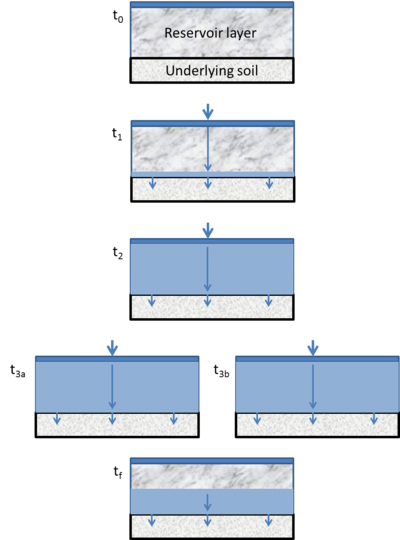
A permeable pavement system without underdrains or with a raised underdrain achieves volume credits by allowing water below the underdrain to infiltrate into the underlying soil. Some infiltration will occur even in systems with underdrains.
- Basis for volume credits
Volume credits for a permeable pavement system are a function of the dimensions of the system, specifically the depth of the subbase below an underdrain, the area of permeable pavement and the porosity of the subbase. Assuming all pore space is available for infiltrating stormwater, the volume credit (Vs) is given by
\(V_s = A_s d_p n\)
where
- As = the surface area of the permeable pavement system (square feet);
- dp = the depth of the reservoir layer, equal to the area from the bottom of the underdrain to the underlying soil (do not include the surfacing thickness)(feet); and
- n = porosity of the subbase(cubic feet/cubic feet).
The volume credit shown above assumes the entire pore space is available for water storage. Although field capacity provides a more accurate estimate of the water stored in a permeable pavement system, field capacity in these systems is assumed to be very low, likely 5 percent or less (see [1]).
Often, permeable pavement will be designed to meet a specific performance goal, such as the 1.1 inch Minimal Impact Design Standards (MIDS) goal for new development sites with no restrictions or a TMDL goal for phosphorus or TSS reductions. Specifications for designing permeable pavement systems, including a discussion of how to calculate the reservoir depth, are provided in the section covering design specifications for permeable pavement.
Infiltration rates for permeable pavement are initially on the order of hundreds of inches per hour, which is much larger than the intensity that can be produced by a rain event. Infiltration rates usually exceed one inch per hour even when the pavement is substantially clogged (Smith and Hunt, 2010). Sites that receive run-on from poorly maintained or disturbed areas had the lowest infiltration rate in a study by Bean et al. 2007. However, the infiltration rates at these sites were still high relative to rainfall intensities.
If a particular storm event exceeds the design storm event, the volume of water infiltrated will exceed the design volume of the permeable pavement system. This is the result of water infiltrating into the underlying soil as precipitation or runoff water continues to be delivered to the system after the design volume has been exceeded. For example, if the performance goal is 1.1 inches and the rain event is 2.0 inches, some of the excess 0.9 inches will be captured by the permeable pavement system. This additional volume infiltrated will be greater for long duration, lower intensity storms compared to a short duration high intensity event. On an annual basis, this additional volume is relatively small.
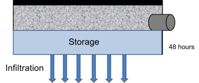
In a system with an underdrain at the bottom, water will infiltrate at a rate dependent on the underlying soil. The volume infiltrated is equal to the infiltration rate multiplied by the time that infiltration occurs. The length of time for a system to drain is controlled by the spacing of underdrains.
Models and calculators for calculating permeable pavement volume credits
The models and calculators discussed below are widely utilized within the stormwater community and are therefore appropriate for calculating volume credits provided the model assumptions are met and the permeable pavement is properly designed, constructed and maintained.
Minimal Impact Design Standards (MIDS) calculator
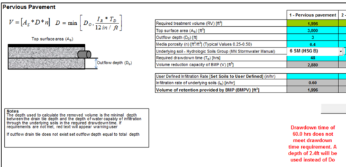
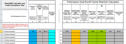
The Minimal Impact Design Standards (MIDS) calculator provides a BMP volume credit based on storage within the reservoir layer (subbase) below the permeable pavement. To calculate the storage volume credit, the design runoff volume needs to be calculated by multiplying the design runoff depth by the new impervious surface area. The Minimal Impact Design Standards (MIDS) performance goal for new sites without restrictions calls for controlling runoff volumes equivalent to 1.1 inches times the new impervious surface. Combined impervious and receiving permeable pavement areas are considered as one practice in the MIDS calculator. Runoff from pervious areas may be routed to permeable pavement and receive credit in the MIDS calculator. Nutrient and sediment emissions must be minimized.
Calculator inputs include
- the area of the permeable pavement surface (square feet);
- the reservoir depth (feet)(also called outflow depth). If the user enters a reservoir depth that will not allow drainage within 24 or 48 hours, the model calculates a depth based on the subbase porosity and the underlying soil;
- porosity of the subbase;
- the underlying soil, which the user selects from a dropdown box (14 options plus an option for a user-defined infiltration rate); and
- the required drawdown time (hours), which the user selects from a drop down box (choices are 24 or 48 hours).
The user can specify an impervious area that contributes to the permeable pavement. The user can also route water through downstream BMPs.
Calculator output includes
- the BMP volume capacity (cubic feet);
- the required retention volume for the specified performance goal (cubic feet);
- the BMP volume credit (cubic feet);
- the untreated volume (cubic feet); and
- the percent water removed relative to the performance goal.
TSS credits
The water quality credits available for installation of permeable pavement depend largely on the design of the storage volume below the pavement and whether or not the runoff is filtered (through underdrain) or infiltrated. The credit for pollutant reduction corresponds directly with annual volume reduction. For example, if a system is designed to store and infiltrate the MIDS performance goal of 1.1 inches off impervious surfaces, it would result in an annual volume reduction of 91% for a site with HSG C subgrade soils, which corresponds to a 91% reduction in TSS. Designs that filter runoff with an underdrain at the bottom of the storage layer (on top of the subgrade) are less effective than infiltration designs. Runoff is filtered while flowing through the permeable pavement and the storage layer and out the underdrain.
Models and calculators for calculating permeable pavement TSS credits
The Manual does not provide specific recommendations for which values or models to use when calculating TSS credits for permeable pavement. The calculators and models discussed below are widely utilized within the stormwater community and are therefore appropriate for calculating TSS credits provided the model assumptions are met and the permeable pavement is properly designed, constructed and maintained.
Minimal Impact Design Standards calculator
If a system is designed to infiltrate the MIDS performance standard of 1.1 inches of runoff from the tributary impervious surfaces, it would result in a 91 percent annual runoff volume reduction from a site with hydrologic soil group (HSG) C soils (infiltration rate of 0.2 inches per hour). Annual pollutant load reductions for this example are approximately equal to the volume reduction. A site with HSG A soils (infiltration rate of 1.6 inches per hour) would result in higher annual reductions.
For designs with underdrains, the reductions are less because a portion of the water is captured by the underdrains before it can be infiltrated. Of the water intercepted and draining through the underdrain, 74 percent (with upper and lower 90 percent confidence bounds of 93 percent and 33 percent, respectively) of total suspended solids removal can be expected.
Since TSS credits are a function of the volume infiltrated, the design dimensions control TSS removal. Calculator inputs include
- the area of the permeable pavement surface (square feet);
- the reservoir depth (feet)(also called outflow depth). If the user enters a reservoir depth that will not allow drainage within 24 or 48 hours, the model calculates a depth based on the subbase porosity and the underlying soil;
- porosity of the subbase;
- the underlying soil, which the user selects from a dropdown box (14 options plus an option for a user-defined infiltration rate); and
- the required drawdown time (hours), which the user selects from a drop down box (choices are 24 or 48 hours).
The user can specify an impervious area that contributes to the permeable pavement. The user can also route water through downstream BMPs.
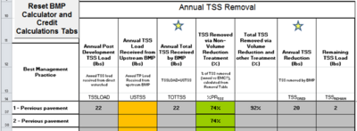
In calculating the TSS credit, the incoming TSS load is first reduced by 74%. This accounts for TSS removal in the case where an underdrain is at the bottom of the permeable pavement system. If an underdrain is suspended above the bottom of the design, then additional reduction in TSS loading will occur as a result of infiltration below the underdrain.
Calculator output includes
- annual post development TSS load in pounds, calculated by multiplying an event mean concentration (EMC) of 55.40 mg/L by the area contributing to the pavement. This area equals impervious surfaces discharging to the permeable pavement plus the direct precipitation onto the pavement;
- TSS removed via non-volume reduction treatment, equal to 74% of the incoming TSS load;
- Total TSS removed via volume reduction and other treatment, given as a percent of incoming TSS;
- Annual TSS reduction in pounds; and
- remaining TSS load, in pounds.
For an example with discussion, see the screen shot on the right.
Literature review on TSS reductions for permeable pavement
This section provides links to research and data on removal of TSS for permeable pavement. Users should be aware of assumptions and limitations associated with data presented in these reports or databases.
- New Jersey Stormwater BMP Manual. 2004. Standards for pervious paving systems. Chapter 9.7.
- Chris Brown, Angus Chu, Bert van Duin,and Caterina Valeo. 2009. Characteristics of Sediment Removal in Two Types of Permeable Pavement. Water Qual. Res. J. Can. 2009 · Volume 44, No. 1, 59-70
- North Carolina Department of Environment and Natural Resources. Water Quality Division. 2012. DWQ Stormwater BMP Manual & BMP Forms. Chapter 18.
- New Hampshire Department of Environmental Services. 2008. New Hampsire Stormwater Manual. Appendix B.
Pollutants other than TSS and phosphorus
In addition to TSS and phosphorus, permeable pavement can reduce loading of the following pollutants:
- Metals such as copper and zinc
- Nitrogen
- Hydrocarbons
- Chloride (indirectly by reducing the amount of road salt applied)
- Oxygen demand
Specific credits and methods for calculating credits are not provided in this section. Information on removal of these pollutant by permeable pavement systems can be found at the following links.
- [2] - information on zinc, copper, lead, nitrate, Kjeldahl nitrogen, and total nitrogen
- [3] - information on total nitrogen, heavy metals, and hydrocarbons.
Related articles
- Overview for permeable pavement
- Types of permeable pavement
- Design criteria for permeable pavement
- Construction specifications for permeable pavement
- Assessing the performance of permeable pavement
- Operation and maintenance of permeable pavement
- Calculating credits for permeable pavement
- Additional considerations for permeable pavement
- References for permeable pavement
- Fact sheets for permeable pavement
