Design criteria for swales Revision as of 16:25, 5 March 2013 by PLeegar (talk | contribs) (Created page with " ==Filtration Overview== <p>Filtration practices are structural stormwater controls that capture, temporarily store, and route stormwater runoff through a filte...")
Contents
- 1 Filtration Overview
- 1.1 Design Criteria
- 1.2 Benefits
- 1.3 Description
- 1.4 Filtration Practices
- 1.5 STORM SEQUENCE
- 1.6 Vegetative Filters
- 1.6.1 Grass Channels
- 1.6.2 Dry Swales
- 1.6.3 Wet Swales
- 1.6.4 Filter Strips
- 1.6.5 Other Filters Not Approved For Minnesota
- 1.6.6 Organic Filter
- 1.6.7 Pocket Filter
- 1.6.8 Submerged Gravel Wetland
- 1.6.9 Retrofit Suitability
- 1.6.10 Special Receiving Waters Suitability
- 1.6.11 Cold Climate Suitability
- 1.6.12 Water Quantity Treatment
- 1.7 Water Quality Treatment
Filtration Overview
Filtration practices are structural stormwater controls that capture, temporarily store, and route stormwater runoff through a filter bed to improve water quality.
Design Criteria
- Ensure adequate space for Filtration system
- Some installations require 2-6 feet of head
- Removal potential of the key pollutant
- Parent material and potential for ground water contamination
Benefits
- Good for highly impervious areas with low sediment/high pollutant load (e.g. urban land use and retrofit scenarios)
- High pollutant removal rates
- May be used in a variety of soil types
- Good for the treatment of hotspots because it can be isolated from ground water if contamination concerns exist Limitations:
- Higher maintenance requirements
- Some installations (media filters) have higher construction costs
- Potential to cause odor problems
- Minimal treatment of soluble nutrients
- Potential for nitrification in media filters where anaerobic conditions exist
Description
Filtration systems vary in their operation and applicability, but all can be described as structural BMPs that function mainly to enhance water quality by passing stormwater through a media. The media can be made of sand, peat, grass, soil, compost or vegetation and should be assigned on a case-by-case basis. Filters can be off-line systems or designed as pre-treatment before discharging to other stormwater features.
The two main categories of filtration systems include: media filters, and vegetated filters. media filters can be located on the surface, underground, along the perimeter or an area, or in what is called a pocket design. Vegetated channels may be grass channels, dry or wet swales, submerged gravel wetlands, or filter strips.
Filtration Practices
STORM SEQUENCE
MANAGEMENT SUITABILITY
- Water Quality (Vwq) = High
- Channel Protection (Vcp) = Med.
- Overbank Flood Protection (Vp10) = Low
- Extreme Flood Protection (Vp100) = Low
- Recharge Volume (Vre) = Med./ Low
MECHANISMS
- Infiltration with appropriate soil & site conditions =
- Screening/ Filtration
- Evaporation
- Transpiration if vegetated
- Soil Adsorption
- Biological/ Micro. Uptake
POLLUTION REMOVAL
70-85% Total Suspended Solids (TSS)
- 0-50%/35% Nutrients - Total Phosphorus /Total Nitrogen
- 45-85% Metals - Cadmium, Copper, Lead, and Zinc
- 35% Pathogens - Coliform, Streptococci, E. Coli
- 80% Toxins - Hydrocarbon
SITE FACTORS
- 5 - AC Max Drainage Area
- 20% - Max. Site Slope
- 3’ - Min. Depth to Bedrock
- 3’- Min. Depth to Seasonally high Water Table
- A,B,C,D -NRCS Soil Type
- Poor - Good Freeze/ Thaw Suitability
- Suitable - Potential Hotspot Runoff requires impermeable liner
Vegetative Filters
Grass Channels
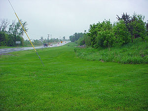
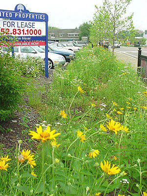
Grass channels are designed to meet a runoff velocity target for a water quality storm as well as the peak discharge from a 2-year design storm. The runoff velocity should not exceed 1.0 fps during the water quality storm. Grass channels can be designed to pass larger storms and serve as conveyance tools. Pre-treatment can be created by placing checkdams across the channel below pipe inflows, and at various other points along the channel. Grass channels do not provide adequate pollutant removal benefits to act as a stand-alone BMP.
Dry Swales
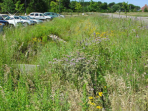
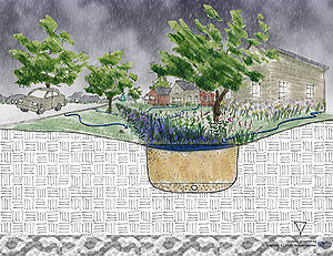
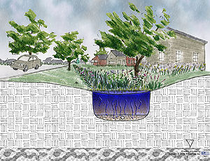
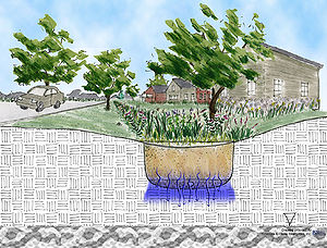
In dry swales, the entire water quality volume is temporarily retained by checkdams during each storm. Unlike the grass channel, the filter bed in the swale is 30 inches of prepared soil. Water is filtered through the sandy loam to under-drains and the swale is quickly dewatered. In the event that surface soils clog, the dry swale has a pea gravel window on the downstream side of each checkdam to route water to the under-drain. Dry swales are often preferred in residential areas because they prevent standing water. See Computer-aided design and drafting (CAD/CADD) drawings for design drawing.
Wet Swales
Wet swales occur when the water table is located very close to the surface. This wet swale acts as a very long and linear shallow wetland treatment system. Like the dry swale, the entire water quality treatment volume is stored within a series of cells created by checkdams. Cells may be planted with emergent wetland plant species to improve pollutant removal.
Filter Strips
Filter strips rely on the use of vegetation to slow runoff velocities and filter out sediment and other pollutants from urban stormwater.
To be effective, however, filter strips require the presence of sheet flow across the entire strip. Once flow concentrates to form a channel, it effectively short-circuits the filter strip. In the most common design, runoff is directed from a parking lot into a long filtering system composed of a stone trench, a grass strip and a longer naturally vegetative strip. The grass portion of the filter strip provides pre-treatment for the wooded portion. In addition, a stone drop can be located at the edge of the parking lot and the filter strip to prevent sediments from depositing at this critical entry point. The filter strip is typically an on-line practice, so it must be designed to withstand the full range of storm events without eroding. Filter strips do not provide adequate pollutant removal benefits to act as a stand-alone BMP. See Computer-aided design and drafting (CAD/CADD) drawings for design drawing.
Other Filters Not Approved For Minnesota
The following filters are not recommended for use in Minnesota due to high probability of failure under cold climate conditions. They are included here for informational purposes only.
Organic Filter
The organic filter functions in much the same way as the surface sand filter, but uses leaf compost or a peat/sand mixture as the filter media instead of sand (compost and peat should not be used when the target pollutant for removal is a dissolved nutrient. The organic material enhances pollutant removal by providing adsorption of heavy metals. In an organic filter, runoff is diverted with a flow splitter into a pre-treatment chamber, from which it passes into one or more filter cells. Each filter bed contains a layer of leaf compost or the peat/sand mixture, followed by a filter fabric and perforated pipe and gravel. Runoff filters through the organic media to the perforated pipe and ultimately to the outlet. The filter bed and subsoils can be separated by an impermeable polyliner to prevent movement into ground water.
Pocket Filter
Pocket sand filters are intended as an inexpensive variation of a sand filter where sediment loads do not warrant a sedimentation chamber and can suffice with a grass filter strip and a plunge pool. The filter bed is comprised of a shallow basin containing the sand filter medium. The filter surface is a layer of soil and a grass cover. In order to avoid clogging the filter has a pea gravel “window” which directs runoff into the sand and a cleanout and observation well. Typically the filtered runoff is allowed to exfiltrate to ground water, although under-drains may be needed if the soils are not suitably permeable.
Submerged Gravel Wetland
Submerged gravel filters consist of a series of cells that are filled with crushed rock or gravel. The standpipe from each cell is set at an elevation that keeps the rock or gravel submerged. Wetland plants are rooted in the media, where they can directly take up pollutants. The anaerobic conditions on the bottom of the filter can foster the de-nitrification process. Submerged gravel wetlands are not recommended for stormwater quality in cold climate conditions, although they do have been used in Minnesota for effluent polishing of wastewater.
Retrofit Suitability
The use of filters as a retrofit practice primarily depends on existing infrastructure and the compatibility of existing storm drain inverts that need to connect to the filter under-drain outflow. In general, four to six feet of elevation above the existing collection system invert is needed for media filter retrofits (2-3 feet is needed for perimeter filters). Underground media filters are excellent for ultra-urban settings where space is at a premium.
Special Receiving Waters Suitability
The "Design restrictions for special waters" table provides guidance regarding the use of filtration practices in areas upstream of special receiving waters. This table is an abbreviated version of a larger table in which other BMP groups are similarly evaluated. The corresponding information about other BMPs is presented in the respective sections of this Manual.
Design restrictions for special waters
Cold Climate Suitability
Various options for use of filtration are available for treating snowmelt runoff. Some of the installations are built below the frost line (trenches, sub-grade proprietary chambers) and do not need further adaptation for the cold. However, some special consideration is HIGHLY RECOMMENDED for surface systems.
The problem with filtration in cold weather is the ice that forms both over the top of the facility and within the soil interstices. To avoid these problems to the extent possible, it is HIGHLY RECOMMENDED that the facility be actively managed to keep it dry before it freezes in the late fall. This can be done by various methods, including limiting inflow, under-drainage, and surface disking.
Proprietary, sub-grade filtration systems provide an alternative to standard surface based systems. Essentially, these systems provide an insulated location for pre-treated snowmelt to be stored and slowly filtered, or simply filtered and drained away if ground water sensitivity is an issue. The insulating value of these systems adds to their appeal as low land consumption alternatives to ponds and surface infiltration basins.
Water Quantity Treatment
Filters are not typically a primary practice for providing water quantity control. They are normally either designed off-line using a flow diversion or configured to safely pass large storm flows while still protecting the filter bed. In limited cases, filters may be able to accommodate the channel protection volume, Vcp, in either an off- or on-line configuration, and in general they do provide some (albeit limited) storage volume. Vegetative filters, in particular, can help reduce detention requirements for a site by providing elongated flow paths, longer times of concentration, and volumetric losses from infiltration and evapo-transpiration. Generally, however, to meet site water quantity or peak discharge criteria, it is HIGHLY RECOMMENDED that another structural control (e.g., detention) be used in conjunction with a filter.
Water Quality Treatment
Filters can be an excellent stormwater treatment practice with the primary pollutant removal mechanism being filtering and settling. Less significant processes can include evaporation, infiltration, transpiration, biological and microbiological uptake, and soil adsorption. Pollutant removal data for select parameters are provided in the Pollutant removal percentages for filtration BMPs table below. “Performance” can also be defined as the quality of the water flowing out of a treatment BMP. These outflow concentrations can be used to assess how well a BMP is performing and what its benefit to a down-gradient receiving water will be. The Pollutant concentrations for filtration BMPs table below contains information on typical expectations for outflow concentration. Please note that Appendix N contains additional explanation for the importance of evaluation outflows from a BMP, as well as how one would adjust performance numbers based on design and operational parameters.
Pollutant removal percentages for filtration BMPs.
Link to this table
| Practice | TSS Low-Med-High | TP Low-Med-High | TN4 | Metals3 (average of Zn and Cu) | Bacteria3 | Hydrocarbons3 |
|---|---|---|---|---|---|---|
| Media Filter1 | 75-85-90 | 30-50-55 | 35 | 80 | 50 | 80 |
| Vegetative Filter2 | see here | see here | 35 | 80 | 0 | 80 |
1 For example, sand, mixed sand/peat and other geologic media
2 Grass filter/swale
3 Not enough information given in databases to differentiate type of filter so both combined for this entry
Typical pollutant effluent concentrations, in milligrams per liter, for filtration BMPs.
Link to this table
| Practice | TSS Low-Med-High4 | TP Low-Med-High4 | TN | Cu | Zn |
|---|---|---|---|---|---|
| Media Filter2 | 5-11-16 | 0.06-0.10-0.19 | 1.1 | 0.008 | 0.060 |
| Vegetative Filter3 | 13-20-44 | 0.15-0.24-0.36 | 1.1 | 0.008 | 0.060 |
1 All concentration values in mg/L which equals parts per million
2 For example, sand, mixed sand/peat and other geologic media
3 Grass filter/swale
4 Not enough information given in databases to differentiate type of filter so both combined for this entry
While it is possible to design media filters to discharge a portion of the effluent to the ground water, they are typically designed as enclosed systems (i.e., no “infiltration”). Vegetative filters, on the other hand, can readily be designed as an effective infiltration/recharge practice, particularly when parent soils have good permeability (> ~ 0.5 in/hr). Consult the Overview of stormwater credits section for more guidance on how to use filters to meet water quality and recharge criteria. Note that the vegetative filters might not meet the 80% TSS removal required by the NPDES Construction permit Part III.C.2.
As noted in the Introduction to stormwater BMPssection discussion of BMP selection, the benefits associated with filtration BMPs should only be accrued based on the amount of water actually passing through the BMP. Excess runoff beyond that designed for the BMP should not be routed through the system because of the potential for hydraulic and particulate over-loading, both of which will adversely impact the life and operation of the BMP.
For example, a filtration device designed to treat the first 0.5” of runoff from a fully impervious surface will catch about 30% of the volume of runoff in the Twin Cities. This means that 70% of the runoff volume should be routed around the filtration system and will not be subject to the removals reflected in the above tables. Attributing removal to all runoff just because a BMP is in place in a drainage system is not a legitimate claim.
Appendix N contains details on how design and operations can either raise or lower the expected level of performance for filtration BMPs.
Limitations
The following general limitations should be recognized when considering installation of a filtration practice:
- Nitrification of water in media filters may occur where aerobic conditions exist.
- Filtration offers limited water quantity control.
- The potential to create odors exists
