![]()
Difference between revisions of "Example for using BMPs in series in the MIDS calculator"
m |
m |
||
| (6 intermediate revisions by the same user not shown) | |||
| Line 1: | Line 1: | ||
| + | [[File:Technical information page image.png|100px|right|alt=image]] | ||
| + | [[File:Pdf image.png|100px|thumb|alt=pdf image|<font size=3>[https://stormwater.pca.state.mn.us/index.php?title=File:Example_for_using_BMPs_in_series_in_the_MIDS_calculator_-_Minnesota_Stormwater_Manual_July_2022.pdf Download pdf]</font size>]] | ||
| + | |||
| + | This page provides an example application of the [[Overview of Minimal Impact Design Standards (MIDS)|Minimal Impact Design Standards (MIDS)]] calculator for several BMPs in series. Examples for individual BMPs can be found at [[MIDS calculator sample exercises]]. | ||
| + | |||
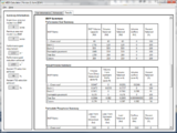
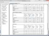
[[file:bmp series table 1.png|thumb|left|300px|alt=table showing BMPs used for this example|<font size=3>Table summarizing BMPs used for this example.</font size>]] | [[file:bmp series table 1.png|thumb|left|300px|alt=table showing BMPs used for this example|<font size=3>Table summarizing BMPs used for this example.</font size>]] | ||
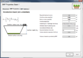
[[file:site schematic.jpg|thumb|300px|alt=schematic for example of bmps in series|<font size=3>Schematic used for the example of BMPs in series for the MIDS calculator. Site properties are illustrated in the table below. See Step 1.</font size>]] | [[file:site schematic.jpg|thumb|300px|alt=schematic for example of bmps in series|<font size=3>Schematic used for the example of BMPs in series for the MIDS calculator. Site properties are illustrated in the table below. See Step 1.</font size>]] | ||
| Line 5: | Line 10: | ||
[[File:site schematic tab.png|thumb|300px|alt=site schematic tab for bmp in series example|<font size=3>Screen shot of schematic tab for the MIDS calculator example of BMPs in series. See Step 3.</font size>]] | [[File:site schematic tab.png|thumb|300px|alt=site schematic tab for bmp in series example|<font size=3>Screen shot of schematic tab for the MIDS calculator example of BMPs in series. See Step 3.</font size>]] | ||
| − | The [http://www.mwmo.org/ Mississippi Watershed Management Organization] office in northeast Minneapolis contains multiple BMPs that are routed to one another before the water reaches the Mississippi River. This site contains a cistern that receives runoff from part of the building’s roof and is used to irrigate a 0.25 acre area, a | + | The [http://www.mwmo.org/ Mississippi Watershed Management Organization] office in northeast Minneapolis contains multiple BMPs that are routed to one another before the water reaches the Mississippi River. This site contains a <span title="A waterproof receptacle for holding liquids, usually water. Cisterns are often built to catch and store rainwater."> '''cistern'''</span> that receives runoff from part of the building’s roof and is used to irrigate a 0.25 acre area, a <span title="Green roofs consist of a series of layers that create an environment suitable for plant growth without damaging the underlying roof system. Green roofs create green space for public benefit, energy efficiency, and stormwater retention/ detention."> '''[https://stormwater.pca.state.mn.us/index.php?title=Green_roofs green roof]'''</span>, a series of <span Title="Tree box filters are widely deployed as stormwater treatment BMPs, normally in stand-alone applications, however can also be used as pretreatment for infiltration, rainwater harvesting, and detention."> '''tree boxes'''</span> that treat overflow from the cistern, <span title="Permeable pavements allow stormwater runoff to filter through surface voids into an underlying stone reservoir for temporary storage and/or infiltration. The most commonly used permeable pavement surfaces are pervious concrete, porous asphalt, and permeable interlocking concrete pavers (PICP)."> '''[https://stormwater.pca.state.mn.us/index.php?title=Permeable_pavement permeable pavement]'''</span>, a <span title="Bioretention, also called rain gardens, is a terrestrial-based (up-land as opposed to wetland) water quality and water quantity control process. Bioretention employs a simplistic, site-integrated design that provides opportunity for runoff infiltration, filtration, storage, and water uptake by vegetation. Bioretention areas are suitable stormwater treatment practices for all land uses, as long as the contributing drainage area is appropriate for the size of the facility. Common bioretention opportunities include landscaping islands, cul-de-sacs, parking lot margins, commercial setbacks, open space, rooftop drainage and street-scapes (i.e., between the curb and sidewalk). Bioretention, when designed with an underdrain and liner, is also a good design option for treating Potential stormwater hotspots. Bioretention is extremely versatile because of its ability to be incorporated into landscaped areas. The versatility of the practice also allows for bioretention areas to be frequently employed as stormwater retrofits."> '''bioretention'''</span> basin without an <span title="An underground drain or trench with openings through which the water may percolate from the soil or ground above"> '''underdrain'''</span> and a bioretention basin with an underdrain. The flow of water and location of the BMPs are displayed in the schematic. All watershed information and BMP parameters for this site are displayed in the tables below. This example will show how to enter all of the BMPs, route them to the appropriate downstream BMP and view the results. |
'''Step 1''': Determine the watershed characteristics for the entire site. For this example we have a 0.8 acre site with 0.43 acres of impervious area and 0.37 acres of turf cover in B soils. | '''Step 1''': Determine the watershed characteristics for the entire site. For this example we have a 0.8 acre site with 0.43 acres of impervious area and 0.37 acres of turf cover in B soils. | ||
| Line 41: | Line 46: | ||
'''Step 10''': Enter in the BMP design parameters into the ''BMP parameters'' tab. Tree trench systems require the following entries. | '''Step 10''': Enter in the BMP design parameters into the ''BMP parameters'' tab. Tree trench systems require the following entries. | ||
| − | *Surface area at [ | + | *Surface area at <span title="Engineered media is a mixture of sand, fines (silt, clay), and organic matter utilized in stormwater practices, most frequently in bioretention practices. The media is typically designed to have a rapid infiltration rate, attenuate pollutants, and allow for plant growth."> [https://stormwater.pca.state.mn.us/index.php?title=Design_criteria_for_bioretention#Materials_specifications_-_filter_media '''engineered media''']</span> surface - 650 square feet |
*Bottom surface area (area at media-soil interface) - 650 square feet | *Bottom surface area (area at media-soil interface) - 650 square feet | ||
*Media depth - 6 feet | *Media depth - 6 feet | ||
| − | * | + | *Media <span title="Field capacity is the amount of soil moisture or water content held in soil after excess water has drained away and the rate of downward movement has materially decreased, which usually takes place within 2–3 days after a rain or irrigation in pervious soils of uniform structure and texture."> '''field capacity'''</span> minus <span title="The wilting point, also called the permanent wilting point, may be defined as the amount of water per unit weight or per unit soil bulk volume in the soil, expressed in percent, that is held so tightly by the soil matrix that roots cannot absorb this water and a plant will wilt."> '''wilting point'''</span> - 0.07 cubic feet per cubic foot |
| − | * | + | *Media <span title="Porosity or void fraction is a measure of the void (i.e. empty) spaces in a material, and is a fraction of the volume of voids over the total volume, between 0 and 1, or as a percentage between 0% and 100%."> '''porosity (f)'''</span> minus field capacity - 0.30 cubic feet per cubic foot |
*[[Plant lists for trees|Tree type]] - Deciduous | *[[Plant lists for trees|Tree type]] - Deciduous | ||
*[[Plant lists for trees|Tree Size]] - Small | *[[Plant lists for trees|Tree Size]] - Small | ||
*Number of Trees - 6 | *Number of Trees - 6 | ||
*Underlying soil – [[Design infiltration rates|Hydrologic Soil Group]] which is SM (HSG B; 0.45 in/hr) from the dropdown box | *Underlying soil – [[Design infiltration rates|Hydrologic Soil Group]] which is SM (HSG B; 0.45 in/hr) from the dropdown box | ||
| − | *Required drawdown time (hrs) - 48 from the dropdown box | + | *Required <span title="The length of time, usually expressed in hours, for ponded water in a stormwater practice to drain. For stormwater practices where water is stored in media, there is no clear definition of drawdown, but an acceptable assumption is the time for water to drain to field capacity"> '''drawdown time'''</span> (hrs) - 48 from the dropdown box |
<gallery caption="MIDS calculator screen shots for BMP Parameter tabs for BMPs used in this example. Click on an image for enlarged view." widths="200px"> | <gallery caption="MIDS calculator screen shots for BMP Parameter tabs for BMPs used in this example. Click on an image for enlarged view." widths="200px"> | ||
| Line 71: | Line 76: | ||
*The media porosity - 0.4 cubic feet per cubic foot | *The media porosity - 0.4 cubic feet per cubic foot | ||
*Will the soil require compaction – No | *Will the soil require compaction – No | ||
| − | *Underlying soil – | + | *Underlying soil – <span title="A soil classification system (Natural Resource Conservation System) based on runoff potential. Groups include A soils (coarse textured with very low runoff potential), B soils (medium coarse textured with low runoff potential), C soils (fine to moderate textured with moderate runoff potential), and D soils (fine textured with high runoff potential)."> '''[https://stormwater.pca.state.mn.us/index.php?title=Design_infiltration_rates hydrologic soil group]'''</span> - 6 SM (HSG B, 0.45 in/hr) |
*Required drawdown time - 48 hours | *Required drawdown time - 48 hours | ||
| Line 142: | Line 147: | ||
file:results tab 4.png|alt=screen shot of results tab|Screen shot of the Results tab for the BMP in series example. See Step 28. | file:results tab 4.png|alt=screen shot of results tab|Screen shot of the Results tab for the BMP in series example. See Step 28. | ||
</gallery> | </gallery> | ||
| + | |||
| + | <noinclude> | ||
| + | [[Category:Level 2 - Case studies and examples/Examples]] | ||
| + | [[Category:Level 3 - Models and modeling/Specific models/MIDS Calculator]] | ||
| + | </noinclude> | ||
Latest revision as of 20:12, 1 December 2022


This page provides an example application of the Minimal Impact Design Standards (MIDS) calculator for several BMPs in series. Examples for individual BMPs can be found at MIDS calculator sample exercises.


The Mississippi Watershed Management Organization office in northeast Minneapolis contains multiple BMPs that are routed to one another before the water reaches the Mississippi River. This site contains a cistern that receives runoff from part of the building’s roof and is used to irrigate a 0.25 acre area, a green roof, a series of tree boxes that treat overflow from the cistern, permeable pavement, a bioretention basin without an underdrain and a bioretention basin with an underdrain. The flow of water and location of the BMPs are displayed in the schematic. All watershed information and BMP parameters for this site are displayed in the tables below. This example will show how to enter all of the BMPs, route them to the appropriate downstream BMP and view the results.
Step 1: Determine the watershed characteristics for the entire site. For this example we have a 0.8 acre site with 0.43 acres of impervious area and 0.37 acres of turf cover in B soils.
Step 2: Fill in the site specific information into the Site Information tab. This includes entering a Zip Code (55418 for this example) and the watershed information in Step 1. Zip code and impervious area must be filled in or an error message will be generated. Other fields on this screen are optional.
Step 3: Go to the Schematic tab and drag and drop the BMPs into the Schematic Window. BMPs in this example include a Harvest and re-use/Cistern, a Tree trench system/Box (w/o underdrain), a permeable pavement BMP, a green roof, a bioretention basin without an underdrain and a bioretention basin with an underdrain.
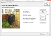
Step 4: Open the BMP properties for the Cistern by right clicking on the Harvest and re-use/Cistern icon and selecting Edit BMP properties, or by double clicking on the Harvest and re-use/Cistern icon.
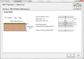
Step 5: Determine the watershed characteristic for the cistern. For this example 0.08 acres of impervious area is draining to the cistern. Enter in the watershed information, change the name to cistern and route to the Tree trench system/Box BMP.
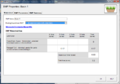
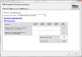
Step 6: Enter in the BMP design parameters into the BMP parameters tab. Harvest and re-use/Cistern requires the following entries:
- Reuse storage volume - equal to the cistern volume of 500
- Irrigation application area - 0.25 acres
- Irrigation application rate - 1 inch/week
- Irrigation start month - May
- Irrigation end month - September
- Does the system go offline during off season – Yes
Step 7: Close the BMP properties window for cistern by clicking OK.
Step 8: Open the BMP properties for the tree box by right clicking on the Tree trench system/Box (w/o underdrain) icon and selecting Edit BMP properties, or by double clicking on the Tree trench system/Box (w/o underdrain) icon.
Step 9: Determine the watershed characteristic for the tree box. The watershed parameters for the tree box include a 0.18 acre site with 0.07 acres of impervious area and 0.11 acres of pervious turf area in type B soils. Enter in the watershed information. Change the name and route the BMP to the bioretention basin without an underdrain.
- MIDS calculator screen shots for watershed tabs for BMPs used in this example. Click on an image for enlarged view.
Screen shot of the watershed tab for the bioretention basin without an underdrain. See Step 17.
Screen shot of the watershed tab for bioretention with an underdrain. See Step 21.
Screen shot of the watershed tab for a cistern. The Harvest and Reuse/Cistern BMP must be used. See Step 5.
Screen shot of the watershed tab for a green roof. See Step 25.
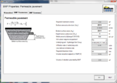
Screen shot of the watershed tab for permeable pavement. See Step 13.
Screen shot of the watershed tab for a tree trench. See Step 9.


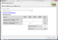
Step 10: Enter in the BMP design parameters into the BMP parameters tab. Tree trench systems require the following entries.
- Surface area at engineered media surface - 650 square feet
- Bottom surface area (area at media-soil interface) - 650 square feet
- Media depth - 6 feet
- Media field capacity minus wilting point - 0.07 cubic feet per cubic foot
- Media porosity (f) minus field capacity - 0.30 cubic feet per cubic foot
- Tree type - Deciduous
- Tree Size - Small
- Number of Trees - 6
- Underlying soil – Hydrologic Soil Group which is SM (HSG B; 0.45 in/hr) from the dropdown box
- Required drawdown time (hrs) - 48 from the dropdown box
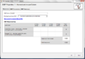
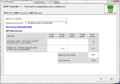
- MIDS calculator screen shots for BMP Parameter tabs for BMPs used in this example. Click on an image for enlarged view.
Screen shot of BMP parameters tab for a cistern. See Step 6.
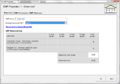
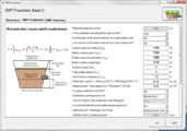
Screen shot of the BMP Parameters tab for biorention with no underdrain (bioinfiltration). See Step 14.
Screen shot of BMP Parameters tab for bioretention with an underdrain (biofiltration). See Step 18.
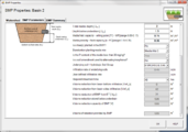
Screen shot of BMP Parameters tab for bioretention with an underdrain (biofiltration). See Step 18.


Step 11: Close the BMP properties window for tree box by clicking OK.
Step 12: Open the BMP properties for the permeable pavement by right clicking on the Permeable pavement icon and selecting Edit BMP properties, or by double clicking on the Permeable pavement icon.
Step 13: Determine the watershed characteristic for the permeable pavement. The watershed parameters for the permeable pavement include a 0.08 acre site with all of it being impervious. Enter in the watershed information. Change the name and route the BMP to the bioretention basin without an underdrain.
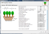
Step 14: Enter in the BMP design parameters into the “BMP parameters” tab. Permeable pavement requires the following entries.
- Surface area at underdrain - 2614 square feet
- Bottom surface area - 2614 square feet
- The depth below the underdrain - 1 foot
- The media porosity - 0.4 cubic feet per cubic foot
- Will the soil require compaction – No
- Underlying soil – hydrologic soil group - 6 SM (HSG B, 0.45 in/hr)
- Required drawdown time - 48 hours

Step 15: Close the BMP properties window for permeable pavement by clicking OK.
Step 16: Open the BMP properties for the Basin 1 by right clicking on the Bioretention basin (w/o an underdrain) icon and selecting Edit BMP properties, or by double clicking on the Bioretention basin (w/o an underdrain) icon.
Step 17: Determine the watershed characteristic for the bioretention basin without an underdrain. The watershed parameters for Basin 1 include a 0.2 acre site with 0.03 acres of impervious area and 0.17 acres of pervious turf area in type B soils. Enter in the watershed information. Change the name and route the BMP to the bioretention basin with an underdrain.
Step 18: Click on the BMP Parameters tab and enter the BMP design parameters. Bioretention basin without an underdrain requires the following entries.
- Overflow surface area - 2200 square feet
- Bottom surface area - 1282 square feet
- Overflow depth - 1 foot
- Underlying soil – Hydrologic Soil Group - SM (HSG B; 0.45 in/hr) from the dropdown box
- Required drawdown time (hrs) - 48 from the dropdown box
- MIDS calculator screen shots for BMP Parameter tabs for BMPs used in this example. Click on an image for enlarged view.
Screen shot of the BMP Parameters tab for green roof. See Step 26.
Screen shot of the BMP parameters tab for permeable pavement. See Step 14.
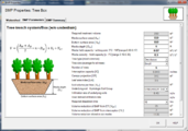
Screen shot of the BMP parameters tab for tree box. See Step 10.
Screen shot of the BMP parameters tab for tree box. See Step 10.


Step 19: Close the BMP properties window for Basin 1 by clicking OK.
Step 20: Open the BMP properties for the Basin 2 by right clicking on the Bioretention basin (with an underdrain) icon and selecting Edit BMP properties, or by double clicking on the Bioretention basin (with an underdrain) icon.
Step 21: Determine the watershed characteristic for the bioretention basin with an underdrain. The watershed parameters for Basin 2 include a 0.27 acre site with 0.15 acres of impervious area and 0.12 acres of pervious turf area in type B soils. Enter in the watershed information and change the name.
Step 22: Enter in the BMP design parameters into the BMP parameters tab. Bioretention basin with an underdrain requires the following entries.
- Is the underdrain elevated above native soils – Yes
- Are the sides of the basin lined with an impermeable liner – No
- Is the bottom of the basin lined with an impermeable liner – No
- Surface area of overflow - 1546 square feet
- Surface area at media surface - 1250 square feet
- Surface area at underdrain -1200 square feet
- Bottom surface area (area at media-soil interface) - 1110 square feet
- Overflow depth - 1 foot
- Total media depth - 3 feet
- Depth below underdrain - 1.3 foot
- Media field capacity minus wilting point - 0.15 cubic feet per cubic foot
- Media porosity minus field capacity - 0.35 cubic feet per cubic foot
- Is a tree(s) planted in the BMP – No
- Bioretention planting media mix - Media Mix C
- Is the P content of the media less than 30 mg/kg - auto fills to “Yes” for Media Mix C
- Is a soil amendment used – No
- Underlying soil – Hydrologic Soil Group - SM (HSG B; 0.45 in/hr) from the dropdown box
- Required drawdown time (hrs) - 48 from the dropdown box
Step 23: Close the BMP properties window for Basin 2 by clicking OK.
Step 24: Open the BMP properties for the green roof by right clicking on the Green roof icon and selecting Edit BMP properties, or by double clicking on the Green roof icon.
Step 25: Determine the watershed characteristic for the green roof. The watershed parameters for the green roof include a 0.02 acre site all impervious. Enter in the watershed information. Change the name and route the green roof to Basin 1.
Step 26: Click on the BMP Parameters tab and enter in the BMP design parameters. Green roof requires two entries.
- The media depth - 4 inches
- The surface area of the green roof - 871 square feet
Step 27: Close the BMP properties window for the green roof. Check the routing by looking at the Schematic tab to make sure all of the BMPs are routed correctly.
Step 28: Go to the Results tab and review the results.
- MIDS calculator screen shots for Results tabs for this example. Click on an image for enlarged view.
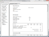
Screen shot of the Results tab for the BMP in series example. See Step 28.
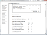
Screen shot of the Results tab for the BMP in series example. See Step 28.
Screen shot of the Results tab for the BMP in series example. See Step 28.
Screen shot of the Results tab for the BMP in series example. See Step 28.


This page was last edited on 1 December 2022, at 20:12.