![]()
Requirements, recommendations and information for using Other as a BMP in the MIDS calculator
The Other BMP allows user-defined stormwater volume and pollutant reduction amounts to be entered. This can be used for BMPs that are not in the calculator. Examples of some BMPs that may be used for this BMP are given at the end of this article. The user must be able to provide evidence and support for each of the stormwater volume and pollutant reduction amounts entered in the Other BMP.
Contents
MIDS calculator user inputs for Other BMP


For the Other BMP, the user must input the following parameters to calculate the stormwater volume and pollutant load reductions associated with the BMP.
- Watershed tab
- BMP Name: this cell is auto-filled but can be changed by the user.
- Routing/downstream BMP: if this BMP is part of a treatment train and water is being routed from this BMP to another BMP, the user selects the name of the BMP from the dropdown box to which water is being routed. All water must be routed to a single downstream BMP. Note that the user must include the BMP receiving the routed water in the Schematic tab or the BMP will not appear in the dropdown box.
- BMP Watershed Area: BMP watershed areas are the areas draining directly to the BMP. Values can be added for four soil types (Hydrologic Soil Groups (HSG) A, B, C, D) and for two Land Cover types (Forest/Open Space and Managed Turf). The BMP area for these two land covers should be included as pervious area in the watershed. Units are in acres.
- BMP Parameters tab
- BMP Volume capacity [V]: The amount of stormwater volume reduction capacity the BMP can provide toward the performance goal. This is an instantaneous volume reduction capacity of the BMP. Units are in cubic feet.
- Annual runoff volume retained: The percent annual stormwater volume reduction provided by the BMP. Units are in percent between 0 and 100 percent.
- Particulate P removal rate via non volume reduction treatment: The percent particulate phosphorus load removal applied to stormwater captured but not removed/retained by the BMP (i.e. water that is routed downstream). Units are in percent between 0 and 100 percent.
- Dissolved P removal rate via non volume reduction treatment: The percent dissolved phosphorus load removal applied to stormwater captured but not removed/retained by the BMP (i.e. water that is routed downstream). Units are in percent between 0 and 100 percent.
- TSS removal rate via non volume reduction treatment: The percent total suspended solids (TSS) load removal applied to stormwater captured but not removed/retained by the BMP (i.e. water that is routed downstream). Units are in percent between 0 and 100 percent.
- BMP Summary Tab: The BMP Summary tab summarizes the volume and pollutant reductions provided by the specific BMP. It details the performance goal volume reductions and annual average volume, dissolved P, particulate P, and TSS load reductions. Included in the summary are the total volume and pollutant loads received by the BMP from its direct watershed, from upstream BMPs and a combined value of the two. Also included in the summary, are the volume and pollutant load reductions provided by the BMP, in addition to the volume and pollutant loads that exit the BMP through the outflow. This outflow load and volume is what is routed to the downstream BMP if one is defined in the Watershed tab. Finally, percent reductions are provided for the percent of the performance goal achieved, percent annual runoff volume retained, total percent annual particulate phosphorus reduction, total percent annual dissolved phosphorus reduction, total percent annual TP reduction, and total percent annual TSS reduction.
Model input requirements and recommendations
The following is a required input into the MIDS calculator. If it is not met, an error message will inform the user to change the input to meet the requirement.
- All annual percent removal rates for stormwater volume and pollutants must be between 0 and 100 percent.
Methodology
Required Treatment Volume
Required treatment volume, or the volume of stormwater runoff delivered to the BMP, equals the performance goal (1.1 inches for MIDS or user-specified performance goal) times the impervious area draining to the BMP plus any water routed to the BMP from another BMP. This stormwater is delivered to the BMP instantaneously.
Volume Reduction
The volume reduction achieved by a BMP compares the volume capacity of the BMP to the required treatment volume. For the Other BMP, the volume reduction capacity of the BMP is entered by the user in the field called BMP volume capacity [V]. The user must therefore know the volume reduction capacity of the BMP (i.e. it is not calculated as with other BMPs in the calculator). Volume of retention provided by BMP is the amount of volume credit the BMP provides toward the performance goal. This value is equal to BMP volume capacity [V] as long as the volume capacity is less than or equal to Required treatment volume. If BMP volume capacity [V] is greater than Required treatment volume, then the BMP volume credit is equal to Required treatment volume. This check makes sure the BMP is not getting credit beyond the performance goal. For example, if the BMP is oversized the user will only receive credit for the required treatment volume routed to the BMP.
Pollutant Reduction
Pollutant load reductions are calculated on an annual basis. For this BMP, the pollutant removal rates are defined by the user. The annual volume reduction is defined by the user. All pollutants associated with stormwater that is reduced on an annual basis are captured for a 100 percent removal. Pollutant reduction rates for total suspended solids (TSS), dissolved phosphorus, and particulate phosphorus are defined by the user and applied to stormwater captured but not reduced/removed by the BMP.
NOTE: The user can modify event mean concentrations (EMCs) on the Site Information tab in the calculator. Default concentrations are 54.5 milligrams per liter for total suspended solids (TSS) and 0.3 milligrams per liter for total phosphorus (particulate plus dissolved). The calculator will notify the user if the default is changed. Changing the default EMC will result in changes to the total pounds of pollutant reduced.
Routing
An Other BMP can be routed to any other BMP, except for a green roof and a swale side slope or any BMP in a treatment sequence that would cause stormwater to be rerouted back to the Other BMP already in that treatment sequence. All BMPs can be routed to an Other BMP, except for a swale side slope.
Assumptions for Other BMP
The following general assumption applies in calculating the credit for an Other BMP. If this assumption is not followed the stormwater volume and pollutant reduction credits cannot be applied.
- It is assumed that values entered into the Other BMP are based on a detailed analysis of the system it represents and that evidence can be provided and defended for each value entered into the Other BMP.
Examples of BMPs that may be used for Other
The following BMPs are not included in the MIDS calculator but may be incorporated using the Other BMP in the calculator.
- Iron enhanced sand filter (Minnesota Filter): this BMP will not achieve volume reductions but will reduce phosphorus and TSS. See the Minnesota Stormwater Manual
- Enhanced turf or disconnected impervious surface: this BMP will achieve volume reductions and pollutant reductions both through infiltration and through filtration. To determine the filtration credits we recommend treating this BMP as a filter strip.
- Sumps/SAFL baffle/grit chambers: These BMPs will not achieve volume reduction. However pollutant reduction can be estimated based on modeling analysis and entered into the calculator.
Example application in the MIDS calculator


This example was completed using Version2 of the Calculator.
An iron enhanced sand filter is going to be constructed in a watershed that contains a 1.4 acre parking lot surrounded by 0.8 acres of pervious area (Turf area). All of the runoff from the watershed will be treated by the sand filter. The soils across the area have a unified soils classification of SM (HSG type B soil). The following steps detail how this system would be set up in the MIDS calculator. Through a literature search and study of the designed iron enhanced sand filter it was determined that the addition of iron in the filter media would provide an additional 60 percent annual dissolved phosphorus load reduction.
Step 1: Determine the watershed characteristics of your entire site. For this example we have a 2.2 acre site with 1.4 acres of impervious area and 0.8 acres of pervious turf area in type B soils. The pervious area includes the area of the sand filter.
Step 2: Fill in the site specific information into the Site Information tab. This includes entering a Zip Code (55414 for this example) and the watershed information from Step 1. Zip code and impervious area must be filled in or an error message will be generated. Other fields on this screen are optional.
Step 3: Go to the Schematic tab and drag and drop the Sand Filter icon and the Other icon into the Schematic Window.
Step 4: Open the BMP properties for the Sand filter by right clicking on the Sand filter icon and selecting Edit BMP properties, or by double clicking on the Sand filter icon.
Step 5: If help is needed, click on the Minnesota Stormwater Manual Wiki link or the Help button to review input parameter specifications and calculation specific to the Sand filter BMP.
Step 6: Determine the watershed characteristics for the sand filter. For this example the entire site is draining to the sand filter. The watershed parameters therefore include a 2.2 acre site with 1.4 acres of impervious area and 0.8 acres of pervious turf area in type B soils. Route the sand filter to the Other BMP. Fill in the BMP specific watershed information (1.4 acres on impervious cover and 0.8 acres of Managed turf in B soils).
Step 7: Design parameters are not required for the sand filter BMP. Click on BMP Summary tab to view results for this BMP. Notice that the sand filter alone does not provide any dissolved phosphorus reduction.
- MIDS calculator screen shots for inputs for Other BMP. Click on an image for enlarged view.
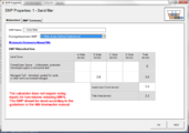
Schematic showing watershed tab for Other BMP. Note the watershed information is entered for the sand filter. See Step 6.
Schematic showing BMP Summary tab for Other BMP. See Step7.
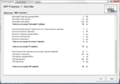
Screen shot of the BMP Summary tab for Other BMP. See Step 7.
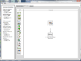
Screen shot of schematic tab showing routing of the sand filter to the Other BMP. See Step 6.


Step 8: Click on the OK button to exit the BMP properties window
Step 9: Open the BMP properties for the Other BMP by right clicking on the Other icon and selecting Edit BMP properties, or by double clicking on the Other icon.
Step 10: if help is needed, click on the Minnesota Stormwater Manual Wiki link or the Help button to review input parameter specifications and calculation specific to the Other BMP.
Step 11: Determine the watershed characteristics for the Other BMP. The Other BMP represents the iron enhancement to the sand filter. Therefore, no additional watershed parameters are needed. Change the name to something descriptive.
Step 12: Determine the BMP design parameters. For the Other BMP the user must define the following.
- BMP volume capacity (0 for a sand filter)
- percent annual runoff volume reduction (0 for a sand filter)
- percent dissolved phosphorus removed annually via non volume reduction treatment (60 percent times the fraction of annual runoff volume that passes through the sand filter; See Calculating credits for iron enhanced sand filter)
- percent particulate phosphorus removed annually via non-volume reduction treatment (0 for a sand filter)
- total suspended sediments (TSS) removed annually via non-volume reduction treatment
For this example the Other BMP represents the added dissolved phophorus removal provided by enhancing the sand media with iron. In the percent dissolved phosphorus removed annual via non volume reduction treatment enter a value of 60 percent.
- MIDS calculator screen shots for inputs for Other BMP. Click on an image for enlarged view.
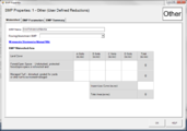
Schematic showing watershed tab for Other BMP. Note the watershed information was entered for the sand filter and is therefore not entered for the Other BMP. See Step 11.
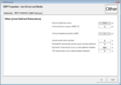
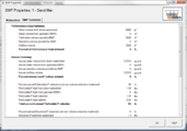
Schematic showing BMP Parameters tab for Other BMP. See Step12.
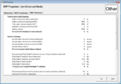
Screen shot of the BMP Summary tab for Other BMP. See Step 13.
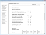
Screen shot of Results tab for the Other BMP. See Step 15.


Step 13: Click on BMP Summary tab to view results for this BMP.
Step 14: Click on the OK button to exit the BMP properties screen.
Step 15: Click on Results tab to see overall results for the site.
Links to MIDS pages
- Overview of Minimal Impact Design Standards (MIDS)
- Performance goals for new development, re-development and linear projects
- Design Sequence Flowchart-Flexible treatment options
- Community Assistance Package
- MIDS calculator
- Performance curves for MIDS calculator
- Training and workshop materials and modules
- Technical documents
This page was last edited on 23 November 2022, at 18:55.