Sediment control practices - Sediment traps and basins
This section of the manual is being developed
Contents
Temporary/Permanent Sediment Traps and Basins
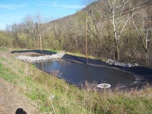
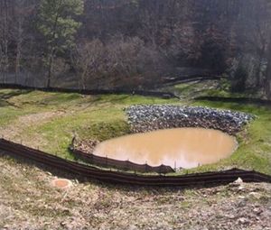
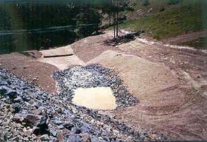
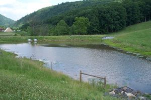
Sediment traps and basins are settling ponds formed by excavation and/or an embankment that intercept and retain sediment-laden runoff from a construction site for a sufficient period of time to allow the majority of sediment to settle out prior to being released from the site. They may be constructed as smaller sediment traps – serving disturbed areas of an acre or less – or as larger sediment basins, handling runoff from subdivisions, commercial/institutional sites, or roadway projects. Proper use of these structures can greatly reduce sediment transport off-site; if properly designed, installed, and maintained, sediment removal efficiency of 80% or greater can be achieved. Sediment traps are often temporary, and usually decommissioned after the disturbed area is stabilized (i.e., with vegetation or other cover). Temporary sediment basins can be converted to permanent stormwater management basins after construction is complete. Sediment traps and basins are very useful on construction sites with moderate to steep slopes, and the selection of traps versus basins primarily depends on the size of the contributing drainage area and plans for post-construction stormwater management, as discussed below.
Purpose and function
Sediment traps retain runoff using embankments and other barriers and discharge through an overflow or piped outlet to a vegetated swale or other drainage feature. Sediment basins are typically larger than sediment traps and may feature earthen embankments that retain runoff for longer periods of time, releasing runoff via floating, perforated, or slotted risers, or when the water level exceeds the height of the riser pipe in the outlet structure.
Applicability
Sediment traps and basins represent one of the most effective and reliable measures for treating sediment-laden runoff from construction sites. These structures are typically placed near the perimeter of the site, where flows concentrate in swales, ditches, or other low areas. Phasing of construction activities should be designed to allow sediment traps and basins to be utilized before upslope areas are disturbed, if possible, and until the contributing drainage area is fully stabilized. Specific considerations related to site applicability and permit applicability are discussed below.
Site applicability
Disturbed soils on a construction site have the potential to leave the site via stormwater runoff and negatively impact bodies of water, roadways, and neighboring property. Therefore, sediment traps and basins should be placed in such a way that they interrupt concentrated or sheet flows of stormwater discharge across a construction site. Sediment traps can be placed near the point of discharge and are often built in series to intercept and treat flow moving down long drainage paths through a site. Stormwater basins should be placed in low lying areas on the outer edge of a construction site where water naturally flows or is directed according to site plans. Sediment traps are extremely useful in perimeter control areas where silt fences will likely fail. Do not site sediment traps in high-velocity flow areas (e.g., culvert outlets, steep ditches) where excessive turbulence and scour erosion may interfere with sediment settling processes. Neither practice should be placed in surface waters (including intermittent streams) or within their required buffer zones.
Permit applicability
Section 14 (Temporary Sediment Basins) of the MPCA Construction Stormwater General Permit (2018) has several requirements regarding sediment basins, including:
- (Section 14.2) Sediment basins are required where ten (10) or more acres of disturbed soil drain to a common location. If the acreage of disturbed soil is reduced to less than ten (10) acres due to establishment of permanent cover, the temporary basin is no longer required. Temporary sediment basins may be converted to permanent basins after completion of construction.
- (Sections 14.3 and 14.4) For each acre of land that drains to the basin, the basin must provide sufficient live storage to hold runoff from a 2-year 24-hour storm event or provide 1,800 cubic feet of live storage, whichever is greater. If storm calculations are not conducted, the temporary basin must provide 3,600 cubic feet of storage for every acre drained.
- (Sections 14.5, 14.6, and 14.7) Outlet structures must be designed to prevent short-circuiting and discharge of floating debris, withdraw water from the surface of the sediment pond, and have sufficient energy dissipation for the outlet within 24 hours after connecting to a surface water.
- (Sections 14.8 and 14.9) Temporary basins must be located outside of surface waters and applicable buffer zone requirements, and temporary basins must be constructed prior to disturbance of ten (10) or more acres of soil draining to a common location.
- (Section 14.10) The general construction permit allows other effective sediment controls (e.g., a series of smaller sediment basins and/or sediment traps, silt fences, vegetative buffer strips, etc.) if sediment basin requirements are infeasible to meet on a particular site. This determination must be documented in the SWPPP.
Specific permit language
Applicability
Specifically, Section 14.2 of the MPCA Construction Stormwater General Permit (2018) states: “Where ten (10) or more acres of disturbed soil drain to a common location, permittees must provide a temporary sediment basin to provide treatment of the runoff before it leaves the construction site or enters surface waters. Permittees may convert a temporary sediment basin to a permanent basin after construction is complete. The temporary basin is no longer required when permanent cover has reduced the acreage of disturbed soil to less than ten (10) acres draining to a common location. “
Sizing
Section 14.3 states: “The temporary basin must provide live storage for a calculated volume of runoff from a two (2)-year, 24-hour storm from each acre drained to the basin or 1,800 cubic feet of live storage per acre drained, whichever is greater.”
Section 14.4 states: “Where permittees have not calculated the two (2)-year, 24-hour storm runoff amount, the temporary basin must provide 3,600 cubic feet of live storage per acre of the basins' drainage area”.
Outlets
Section 14.5 states: “Permittees must design basin outlets to prevent short-circuiting and the discharge of floating debris.”
Section 14.6 states: “Permittees must design the outlet structure to withdraw water from the surface to minimize the discharge of pollutants. Permittees may temporarily suspend the use of a surface withdrawal mechanism during frozen conditions. The basin must include a stabilized emergency overflow to prevent failure of pond integrity.”
Section 14.7 states: “Permittees must provide energy dissipation for the basin outlet within 24 hours after connection to a surface water.”
Location and timing
Section 14.8 states: “Permittees must locate temporary basins outside of surface waters and any buffer zone required in item 23.11 [of the general permit].”
Section 14.9 states: “Permittees must construct the temporary basins prior to disturbing 10 or more acres of soil draining to a common location.”
Alternatives
Section 14.10 states: “Where a temporary sediment basin meeting the requirements of item 14.3 through 14.9 is infeasible, permittees must install effective sediment controls such as smaller sediment basins and/or sediment traps, silt fences, vegetative buffer strips or any appropriate combination of measures as dictated by individual site conditions. In determining whether installing a sediment basin is infeasible, permittees must consider public safety and may consider factors such as site soils, slope, and available area on-site. Permittees must document this determination of infeasibility in the SWPPP”.
Additional information on basin drainage is provided in “Dewatering practices.” <MPCA, this should be linked to the Dewatering Practices wiki page>
Effectiveness
When designed, installed, and maintained properly, sediment traps and basins have relatively good sediment-trapping efficiencies (typically between 60 and 80%) and need little maintenance compared to other practices used to treat sediment-laden runoff as long as upland areas are brought to final grade and stabilized promptly. Sediment traps and basins provide good control of coarse sediment and are moderately effective for trapping medium-size sediment particles. However, they have a relatively low trapping efficiency for fine silt and clay particles suspended in runoff. Longer detention times, use of a flocculant, or additional sediment control measures may be necessary for their removal. In general, the larger the storage volume and the longer the detention time of the stormwater, the more efficient sediment basins are at removing finer particles. Oil, grease, and other floatables may also be removed if an outlet pipe is used that features perforated openings, a screen, a skimmer, or other means to draw ponded water from just below the surface. Effectiveness in removing floatables is completely dependent on the outlet design.
Expected performance for temporary/permanent sediment traps and basins.
Link to this table
| Water quantity | |
|---|---|
| Flow attenuation | Secondary design benefit |
| Runoff volume reduction | Secondary design benefit |
| Water quality | |
| Erosion prevention | Little or no design benefit |
| Sediment control | Primary design benefit |
| Nutrient loading | Secondary design benefit |
| Pollutant removal | |
| Total suspended solids | Primary design benefit |
| Total phosphorus | Secondary design benefit |
| Heavy metals | Secondary design benefit |
| Floatables | Secondary design benefit |
| Oil and grease | Secondary design benefit |
Planning Considerations
Sediment Traps
A well-functioning and well-placed sediment trap is key to preventing off-site migration of sediment. They should be installed early on in the project before the site clearing phase begins. The natural drainage of a construction site should be considered prior to planning sediment trap size and location. Locate areas of potential sediment runoff, determine the likely pathway for water draining from those sites, and place sediment traps between the source of sediment and the site perimeter or water body that will receive the runoff. For maximum effectiveness, sediment traps should be placed as close as possible to the source of sediment runoff. If the site configuration prevents the use of a single sediment trap, multiple smaller traps arranged in series can be used to meet the design requirement.
Sediment Basins
If sediment traps are not sufficient for stormwater and sediment control, sediment basins should be used due to their larger capacity. Basins have a larger footprint than sediment traps and should be sited at a low point on the construction site, where runoff converges. If stormwater does not naturally flow towards the sediment basin and cannot feasibly be directed to it, a series of sediment traps or other BMPs may be more appropriate for sediment control. It is recommended that the slopes around the basin be greater than 1% but no more than 25% to promote flow towards the basin. Similar to sediment traps, sediment basins should be installed early on in the project prior to soil disturbing activities wherever possible. When selecting an area to place a sediment basin, look for areas that meet the following recommendations:
1) Capable of storing sediment and stormwater from as much of the planned disturbed area as practical,
2) Provide access for maintenance throughout the project,
3) Are far enough away (minimum of 20 feet of separation) from existing building foundations to preserve their integrity,
4) Where groundwater levels will be lower than the basin bottom,
5) Limit treatment to runoff from disturbed areas only, and
6) Minimally interfere with the construction site.
Temporary sediment basins are often converted to permanent stormwater management structures once all disturbed contributory drainage areas have been permanently stabilized and approved by a stormwater inspection entity and all storm drains have been flushed. The outlet structure must be installed in accordance with an approved stormwater management design plan. Additional grading may be necessary to achieve the required storage volume of the basin. Prior to transition to a post-construction stormwater basin, the basin must be cleared of accumulated sediment, fully stabilized, and inspected to ensure that side slopes and the volume, containment berm, outlet, and inlets comply with stormwater basin design requirements.
Design
Sediment traps
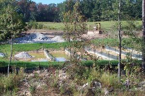
A temporary sediment trap should only be used in a location with a drainage area of five (5) acres or less and where it will be used for two years or less.
Sediment traps must have an outlet to carry runoff from the structure. The outlet can be a pipe outlet, stabilized rock outlet, or other suitable structure. The outlet must be capable of handling the runoff from a 2-year-frequency, 24-hour-duration storm without failure or significant erosion. Overflow outlets should be stabilized with coarse aggregate and/or riprap and geotextile fabric.
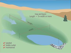
Sediment trap sizing is dependent on the anticipated drainage area and volume of stormwater to treat. A side slope ratio of 2:1 or flatter is recommended for sediment traps. A minimum length to width ratio of 2:1 should be provided, and the distance between the inlet and outlet should be maximized to increase sediment removal efficiency. Where flow paths are shortened due to tight site conditions, silt fencing can be used as baffles within the trap to slow flows through the trap and increase sediment removal.
The example design table below provides general guidance on sizing sediment traps based on contributing drainage area. As a rule of thumb, a total storage volume of 3,600 ft3 should be provided for every acre of contributing drainage. This volume may be equally divided between wet (retention) and dry (drawdown, or dewatered) storage. Wet storage is provided in a permanent pool and dry storage provides extended settling time.
Sediment trap sizing table (Source: adapted from District of Columbia Erosion and Sediment Control Manual, 2017)
Sediment trap sizing table
Link to this table
| Drainage area (ac) | Total Volume (ft3) | Wet Volume (ft3) | Dry Volume (ft3) | Minimum Depth (ft) | Depth of Permanent Pool (ft) | Minimum Bottom Length (ft) | Minimum Bottom Width |
|---|---|---|---|---|---|---|---|
| 1 | 3600 | 1800 | 1800 | 2.5 | 1.5 | 46 | 23 |
| 2 | 7200 | 3600 | 3600 | 2.75 | 1.5 | 64 | 32 |
| 3 | 10800 | 5400 | 5400 | 3.0 | 1.75 | 76 | 38 |
Table assumes 2:1 side slopes; Minimum depth is from trap bottom to weir crest and includes both wet and dry storage
Embankments are located at the lowest point of the sediment trap and typically consist of mixed size rock or a stabilized earthen berm with a rock-armored overflow notch. The bottom of the embankment should be level with the wet storage portion of the trap. The design table below summarizes the recommended embankment top width (also referred to as weir length) for sediment traps as a function of contributing drainage area.
Recommended embankment widths for sediment traps (Source: Iowa Statewide Urban Design and Specification Design Manual, 2013 Revision)
Recommended embankment widths for sediment traps
Link to this table
| Contributing Drainage Area (acre) | Embankment Width (ft) |
|---|---|
| 1 | 4 |
| 2 | 6 |
| 3 | 8 |
| 4 | 10 |
| 5 | 12 |
