Difference between revisions of "Bioretention terminology"
(Created page with "Differences between infiltration basins and bioretention basins") |
m |
||
| (78 intermediate revisions by 2 users not shown) | |||
| Line 1: | Line 1: | ||
| − | [[Differences between infiltration basins and bioretention basins]] | + | [[File:Pdf image.png|100px|thumb|alt=pdf image|<font size=3>[https://stormwater.pca.state.mn.us/index.php?title=File:Bioretention_terminology_-_Minnesota_Stormwater_Manual_feb_2021.pdf Download pdf]</font size>]] |
| + | [[File:General information page image.png|right|100px|alt=image]] | ||
| + | [[File:Determining type of infiltration SCM 2.png|thumb|300px|alt=flowchart for determining the type of infiltration or bioretetnion device|<font size=3>Flow chart for determining the type of infiltration or bioretention device.</font size>]] | ||
| + | |||
| + | <span title="Infiltration basins, infiltration trenches, dry wells, and underground infiltration systems capture and temporarily store stormwater before allowing it to infiltrate into the soil. As the stormwater penetrates the underlying soil, chemical, biological and physical processes remove pollutants and delay peak stormwater flows."> [https://stormwater.pca.state.mn.us/index.php?title=Infiltration '''Infiltration basins''']</span> and <span title="Bioretention, also called rain gardens, is a terrestrial-based (up-land as opposed to wetland) water quality and water quantity control process. Bioretention employs a simplistic, site-integrated design that provides opportunity for runoff infiltration, filtration, storage, and water uptake by vegetation. Bioretention areas are suitable stormwater treatment practices for all land uses, as long as the contributing drainage area is appropriate for the size of the facility. Common bioretention opportunities include landscaping islands, cul-de-sacs, parking lot margins, commercial setbacks, open space, rooftop drainage and street-scapes (i.e., between the curb and sidewalk). Bioretention, when designed with an underdrain and liner, is also a good design option for treating Potential stormwater hotspots. Bioretention is extremely versatile because of its ability to be incorporated into landscaped areas. The versatility of the practice also allows for bioretention areas to be frequently employed as stormwater retrofits."> '''bioretention basins'''</span> are terrestrial-based (up-land as opposed to wetland-based), water quality and water quantity control treatment practices with a required <span title="The length of time, usually expressed in hours, for ponded water in a stormwater practice to drain. For stormwater practices where water is stored in media, there is no clear definition of drawdown, but an acceptable assumption is the time for water to drain to field capacity"> '''drawdown time'''</span>. For basins within trout stream watersheds, the drawdown time is 24 hours or less due to the need to reduce discharge temperatures. | ||
| + | |||
| + | Although the difference between infiltration basins and the type of bioretention basin is not always clear, the adjacent figure and tables provide some clarity to differentiating between these stormwater control devices. Section drawings are included at the bottom of this page. Note the second table below provides a comparison of terminology used in this Manual with terminology used in the earlier versions of the Manual. | ||
| + | |||
| + | {{:Differences between infiltration basins and bioretention basins}} | ||
| + | |||
| + | {{:Types of bioretention basins}} | ||
| + | |||
| + | <gallery caption="Section drawings for different bioretention devices. Click on an image for enlarged view. Also see [[Bioretention plan and section drawings]]." widths="160px"> | ||
| + | File:Bioinfiltration.png|alt=image of bioinfiltration device|Bioinfiltration device | ||
| + | File:Biofiltration with elevated underdrain.png|alt=image of biofiltration device with elevated underdrain|Biofiltration device with elevated underdrain | ||
| + | File:Biofiltration with underdrain at bottom.png|alt=image of biofiltration device with an underdrain at the bottom|Biofiltration device with an underdrain at the bottom | ||
| + | File:Biofiltration with internal water storage.png|alt=image of biofiltration device with internal water storage|Biofiltration device with internal water storage | ||
| + | File:Bioretention with liner.png|alt=image of bioretention device with a liner|Biofiltration device with a liner | ||
| + | </gallery> | ||
| + | |||
| + | [[File:Stillwater rain garden 1.JPG|thumb|300px|alt=photo showing a rain garden in a residential area|<font size=3>A bioretention facility (rain garden) in a residential area. Note the curb cut that allows water to enter the facility.</font size>]] | ||
| + | |||
| + | ==General discussion of types of bioretention BMPs== | ||
| + | As bioretention becomes a more common tool in the stormwater management toolbox and as the number of design variants increases, so does the number of names for each of these variants. As an example of the ongoing evolution of bioretention terminology, the terms “rain garden” and “rainwater garden” have recently caught on with the public and are being used interchangeably with bioretention. In most instances, rain garden designs are utilizing the processes of bioretention, but the term rain garden is also being loosely used to describe BMPs that are operating more as stormwater ponds (or as other BMPs) than as bioretention facilities. | ||
| + | |||
| + | ===Bioinfiltration with no underdrain=== | ||
| + | [[File:Bioinfiltration.png|thumb|300px|alt=image of bioinfiltration device|<font size=3>Bioinfiltration device</font size>]] | ||
| + | |||
| + | Bioinfiltration is suitable for areas where significant recharge of groundwater is possible and would be beneficial. Because there is no underdrain the in-situ soils need to have a high infiltration rate to accommodate the inflow levels. The infiltration rate of the in-situ soils must be determined through proper [[Design criteria for bioretention|soil testing/diagnostics]]. The ''Recommended'' filter media (<span title="Engineered media is a mixture of sand, fines (silt, clay), and organic matter utilized in stormwater practices, most frequently in bioretention practices. The media is typically designed to have a rapid infiltration rate, attenuate pollutants, and allow for plant growth."> [https://stormwater.pca.state.mn.us/index.php?title=Design_criteria_for_bioretention#Materials_specifications_-_filter_media '''engineered media''']</span>) depth is 2.5 feet or more to allow adequate filtration processes to occur. Most [[Design criteria for bioretention#Materials specifications - filter media|media mixes]] are suitable because phosphorus is not a significant concern with this practice. The [https://stormwater.pca.state.mn.us/index.php?title=Construction_stormwater_program Construction General Permit] requires that water captured by the BMP be drawn down within 48 hours. <span title="A soil classification system (Natural Resource Conservation System) based on runoff potential. Groups include A soils (coarse textured with very low runoff potential), B soils (medium coarse textured with low runoff potential), C soils (fine to moderate textured with moderate runoff potential), and D soils (fine textured with high runoff potential)."> '''[https://stormwater.pca.state.mn.us/index.php?title=Design_infiltration_rates Hydrologic soil group]'''</span> A and B soils are commonly suitable for bioinfiltration. Bioinfiltration is suitable for areas and land uses that are expected to generate nutrient runoff (e.g. residential and business campuses) that can be infiltrated and captured by the practice. Fresh mulch rather then aged shredded bark mulch can be used to enhance <span title="The loss or removal of nitrogen or nitrogen compounds specifically : reduction of nitrates or nitrites commonly by bacteria (as in soil) that usually results in the escape of nitrogen into the air.> '''denitrification'''</span> processes if nitrate leaching is a concern. Bioinfiltration is not recommended for <span title="Stormwater Hotspots (PSHs) are activities or practices that have the potential to produce relatively high levels of stormwater pollutants"> '''[https://stormwater.pca.state.mn.us/index.php?title=Potential_stormwater_hotspots potential stormwater hotspots]'''</span>. Other [[Stormwater infiltration and constraints on infiltration|infiltration constraints]] apply to bioinfiltration practices. | ||
| + | |||
| + | ===Biofiltration with underdrain at bottom=== | ||
| + | [[File:Biofiltration with underdrain at bottom.png|thumb|300px|alt=image of biofiltration device with an underdrain at the bottom|<font size=3>Biofiltration device with an underdrain at the bottom</font size>]] | ||
| + | |||
| + | This bioretention practice is designed with an underdrain at the invert of the planting soil mix to ensure drainage at a desired rate. The practice allows for partial recharge and an impervious liner is not used. The depth is also shallow (2.5 feet) to allow high capacity flows if necessary. Siting is suitable for visually prominent or gateway locations in a community. The practice is suitable for areas and land uses that are expected to generate metals loadings (e.g. residential, business campus, or parking lots). The practice is suitable for areas with high nutrient loadings provided the media has a low phosphorus concentration or phosphorus-sorbing amendments are used (see [[Design criteria for bioretention#Materials specifications - filter media|section on filter media]]). This type of facility is also recommended for soils where infiltration is limited (C and D soils). Some volume reduction will be seen from <span title="Loss of water to the atmosphere as a result of the joint processes of evaporation and transpiration through vegetation"> '''evapotranspiration'''</span> and partial infiltration below the underdrain. | ||
| + | |||
| + | ===Biofiltration with elevated underdrain=== | ||
| + | [[File:Biofiltration with elevated underdrain.png|thumb|left|300px|alt=image of biofiltration device with elevated underdrain|<font size=3>Biofiltration device with elevated underdrain</font size>]] | ||
| + | |||
| + | A biofiltration practice with a raised underdrain provides a storage area below the invert of the underdrain discharge pipe. This area provides a recharge zone and quantity control can also be augmented with this storage area. The storage area is equal to the void space of the material used. Since the practice utilizes both infiltration and an underdrain, considerations include those for both bioinfiltration practices and biofiltration with an underdrain at the bottom. These include an assessment of [[Stormwater infiltration and constraints on infiltration|infiltration constraints]] and [[design criteria for bioretention#Materials specifications - filter media|media]]. | ||
| + | |||
| + | ===Biofiltration with a liner (at bottom and or on sides)=== | ||
| + | [[File:Bioretention with liner.png|thumb|300px|alt=image of bioretention device with a liner|<font size=3>Biofiltration device with a liner</font size>]] | ||
| + | |||
| + | This type of facility is recommended for areas that are known as [[Potential stormwater hotspots|potential stormwater hot spots]] (e.g. gas stations, transfer sites, and transportation depots). An important feature of this type of facility is the impervious liner designed to reduce or eliminate the possibility of groundwater contamination. The facility provides a level of treatment strictly through filtration processes that occur when the runoff moves through the soil material to the underdrain discharge point. In the event of an accidental spill, the underdrain can be blocked and the objectionable materials siphoned through an observation well and safely contained. | ||
| + | |||
| + | ===Biofiltration with internal water storage=== | ||
| + | [[File:Biofiltration with internal water storage.png|thumb|300px|alt=image of biofiltration device with internal water storage|<font size=3>Biofiltration device with internal water storage</font size>]] | ||
| + | |||
| + | The biofiltration practice with internal water storage is not commonly used in the Midwestern United States but is widely used in some places on the east coast, such as North Carolina. The use of an upturned elbow in this practice allows water to be retained within the practice, leading to increased pollutant removal, increased infiltration, and increased evapotranspiration. The practice is particularly effective at removing nitrogen through denitrification. The media should be 3 feet or more thick to allow water to be drawn down below the root zone. Underlying soils should be permeable enough to allow water stored within the practice to infiltrate. | ||
| + | |||
| + | ==Specific design applications for various land uses== | ||
| + | It should be noted that the layout of the bioretention area will vary according to individual sites, and to specific site constraints such as underlying soils, existing vegetation, drainage, location of utilities, sight distances for traffic, and aesthetics. Designers are encouraged to be creative in determining how to integrate bioretention into their respective site designs. With this in mind, the following are presented as alternative options. | ||
| + | |||
| + | ===On-lot bioretention=== | ||
| + | Simple design that incorporates a planting bed in the low portion of the site. On-lot systems are designed to receive flows from gutters, and/or other impervious surfaces. | ||
| + | |||
| + | ===Parking lot islands (curbless)=== | ||
| + | In a paved area with no curb, pre-cast car-stops or a “ribbon curb” can be installed along the pavement perimeter to protect the bioretention area. This application of bioretention should only be attempted where shallow grades allow for sheet flow conditions over level entrance areas. Water may be pooled into the parking area where parking spaces are rarely used to achieve an element of stormwater quantity control beyond the confines of the bioretention surface area (Prince George’s County, 2002). | ||
| + | |||
| + | [[file:Bioretention parking lot island.jpg|thumb|300px|alt=schematic showing a bioretention parking lot island|<font size=3>A bioretention parking lot island. Note the use of other BMPs, including permeable pavement and tree trenches. (Source: [http://www.minnehahacreek.org/ Minnehaha Creek Watershed District</font size>])]] | ||
| + | |||
| + | ===Parking lot islands (curb-cut)=== | ||
| + | For curb-cut entrance approaches, the water is diverted into the bioretention area through the use of an inlet deflector block, which has ridges that channel the runoff into the bioretention area ([[References for bioretention|Prince George’s County]], 2002). Special attention to erosion control and pre-treatment should be given to the concentrated flow produced by curbcuts. | ||
| + | |||
| + | ===Road medians / traffic islands=== | ||
| + | A multifunctional landscape can be created by utilizing road medians and islands for bioretention. There is no minimum width recommended for traffic islands from street edge to edge. A buffer may be necessary along the outside curb perimeter to minimize the possibility of drainage seeping under the pavement section, and creating “frost heave” during winter months. Alternately, the installation of a geotextile filter fabric “curtain wall” along the perimeter of the bioretention island will accomplish the same effect. | ||
| + | |||
| + | ===Tree pits / tree box filters=== | ||
| + | [[File:Tree box filter.jpg|thumb|300px|alt=schematic of a tree box filter|<font size=3>A tree box filter. Note the curb cuts. (Source: [http://www.minnehahacreek.org/ Minnehaha Creek Watershed District])</font size>]] | ||
| + | |||
| + | {{alert|For a detailed discussion of bioretention practices that utilize trees, including design, construction, and O & M practices, see the section on [[Trees|trees]].|alert-info}} | ||
| + | |||
| + | Tree pits and tree box filters afford many opportunities for bioretention. Designs vary widely from simple “tree pits”, used for local drainage interception to more formal tree box filters, which are a useful tool for highly urbanized streetscapes. | ||
| + | |||
| + | The tree pit technique provides very shallow storage areas in a “dished” mulch area around the tree or shrub. Typically, the mulched area extends to the dripline for the tree and is similar to conventional mulching practices, except that the mulch area is depressed at least 2 to 3 inches rather than mounded around the tree ([[References for bioretention|Low Impact Design Center]], 2005). | ||
| + | |||
| + | Tree box filters are bioretention areas installed beneath trees that can be very effective at controlling runoff, especially when distributed throughout the site. Runoff is directed to the tree box, where it is cleaned by vegetation and soil before entering a catch basin. The runoff collected in the tree-boxes helps irrigate the trees. The system consists of a container filled with a soil mixture, a mulch layer, under-drain system and a shrub or tree. Stormwater runoff drains directly from impervious surfaces through a filter media. Treated water flows out of the system through an underdrain connected to a storm drainpipe/inlet or into the surrounding soil. Tree box filters can also be used to control runoff volumes/flows by adding storage volume beneath the filter box with an outlet control device ([[References for bioretention|Low Impact Design Center]], 2005). | ||
| + | |||
| + | <noinclude> | ||
| + | |||
| + | ==Related pages== | ||
| + | *[[Bioretention terminology]] (including types of bioretention) | ||
| + | *[[Overview for bioretention]] | ||
| + | *[[Design criteria for bioretention]] | ||
| + | *[[Construction specifications for bioretention]] | ||
| + | *[[Operation and maintenance of bioretention]] | ||
| + | *[[Assessing the performance of bioretention]] | ||
| + | *[[Cost-benefit considerations for bioretention]] | ||
| + | *[[Calculating credits for bioretention]] | ||
| + | *[[Soil amendments to enhance phosphorus sorption]] | ||
| + | *[[Summary of permit requirements for bioretention]] | ||
| + | *[[Supporting material for bioretention]] | ||
| + | *[[External resources for bioretention]] | ||
| + | *[[References for bioretention]] | ||
| + | *[[Requirements, recommendations and information for using bioretention with no underdrain BMPs in the MIDS calculator]] | ||
| + | *[[Requirements, recommendations and information for using bioretention with an underdrain BMPs in the MIDS calculator]] | ||
| + | |||
| + | [[Category:Level 2 - General information, reference, tables, images, and archives/Reference]] | ||
| + | [[Category:Level 3 - Best management practices/Structural practices/Bioretention]] | ||
| + | [[Category:Level 3 - Best management practices/Guidance and information/BMP types and terminology]] | ||
| + | </noinclude> | ||
Latest revision as of 18:50, 15 August 2022
Infiltration basins and bioretention basins are terrestrial-based (up-land as opposed to wetland-based), water quality and water quantity control treatment practices with a required drawdown time. For basins within trout stream watersheds, the drawdown time is 24 hours or less due to the need to reduce discharge temperatures.
Although the difference between infiltration basins and the type of bioretention basin is not always clear, the adjacent figure and tables provide some clarity to differentiating between these stormwater control devices. Section drawings are included at the bottom of this page. Note the second table below provides a comparison of terminology used in this Manual with terminology used in the earlier versions of the Manual.
Summary of factors that can be used to determine differences between infiltration basins and bioretention basins. This table corresponds with Table 1 in the adjacent flowchart.
Link to this table
| BMP | Typical position in watershed | Treatment scale | Typical storm sizes | Maximum drainage area guidelines | Maximum ponding depth guidelines | Growing medium |
|---|---|---|---|---|---|---|
| Infiltration (basin, trench, underground, dry well) | Downgradient of other water quantity or water quality control practices | Development or regional scale control | Less frequent large storm events that exceed capacity of upgradient practices | 50 acres | 4 feet | Native soil |
| Bioretention basin | Located throughout the watershed | Site scale control | Small storms (water quality events) | Typically 5 acres | Ideally 12 inches; can be up to 18 inches with appropriate design and plant selection | Engineered growing medium |
Types of bioretention basins. This table corresponds with Table 2 in the adjacent flowchart.
Link to this table
| BMP | Typical uses; advantages | Relative amount of runoff abstracted from storm sewer system | 2008 Manual terminology1 |
|---|---|---|---|
| Bioinfiltration basin | Abstracts all runoff captured in the basin that does not leave through overflow | All runoff that flows into the basin and does not overflow into an overflow structure is abstracted from the stormsewer system through infiltration or evapotranspiration. | Infiltration / recharge facility |
| Biofiltration basin with underdrain at bottom | Allows for a small amount of infiltration, at a rate compatible with underlying soils, but carries away excess waterthrough the underdrain after it has been filtered through the basin | A small amount of the runoff that flows into the basin and does not overflow into an overflow structure is abstracted from the stormsewer system through infiltration or evapotranspiration; the remainder is filtered by the growing medium but then leaves via an underdrain. | Filtration / partial recharge |
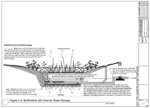
| Biofiltration basin with internal water storage (IWS) | Allows for more infiltration, at a rate compatible with underlying soils, but carries away excess water through the underdrain after it has been filtered through the basin; Internal Water Storage Zone (IWS) (1) allows for more infiltration and evaporation compared to bioretention with underdrain at the bottom; (2) improves thermal pollution abatement and nitrogen removal (longer retention time allows runoff to cool more before discharge and allows denitrification to occur under anoxic condition). | More of the runoff that flows into the basin and does not overflow into an overflow structure is abstracted from the stormsewer system through infiltration or evapotranspiration compared to bioretention with an underdrain at the bottom of the basin without an upturned elbow, because the upturned elbow increases hydraulic retention time; the remainder is filtered by the growing medium but then leaves via an underdrain with an upturned elbow. | Not included |
| Biofiltration basin with elevated underdrain | Allows for more infiltration, at a rate compatible with underlying soils, but carries away excess water through the underdrain after it has been filtered through the basin; elevating underdrain (1) allows for more infiltration and evaporation compared to bioretention with underdrain at the bottom (2) improves thermal pollution abatement and nitrogen removal (longer retention time allows runoff to cool more before discharge and allows denitrification to occur under anoxic condition). | More of the runoff that flows into the basin and does not overflow into an overflow structure is abstracted from the stormsewer system through infiltration or evapotranspiration compared to bioretention with an underdrain at the bottom of the basin, because the elevated underdrain increases hydraulic retention time; the remainder is filtered by the growing medium but then leaves via an elevated underdrain. | Infiltration / filtration / recharge |
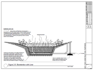
| Biofiltration basin with liner | Impervious liner reduces or eliminates possibility of groundwater contamination; underdrain can be blocked and objectionable materials siphoned through an observation well and safely contained; often used in areas of potential stormwater “hot-spots” (e.g., gas stations, transfer sites, transportation depots,industrial complexes etc.), or areas where groundwater recharge is undesirable | None of the runoff that flows into the basin is abstracted from the stormsewer system through infiltration but some is abstracted through evapotranspiration; i.e. all of the runoff that flows into the basin without flowing into an overflow structure, and is not evapotranspired, is filtered by the growing medium but then leaves via an underdrain. | Filtration only |
1Terminology used in the 2008 Minnesota Stormwater Manual.
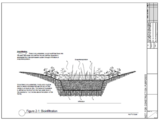
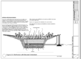
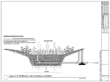
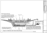
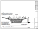
- Section drawings for different bioretention devices. Click on an image for enlarged view. Also see Bioretention plan and section drawings.
Contents
General discussion of types of bioretention BMPs
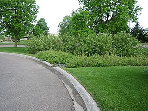
As bioretention becomes a more common tool in the stormwater management toolbox and as the number of design variants increases, so does the number of names for each of these variants. As an example of the ongoing evolution of bioretention terminology, the terms “rain garden” and “rainwater garden” have recently caught on with the public and are being used interchangeably with bioretention. In most instances, rain garden designs are utilizing the processes of bioretention, but the term rain garden is also being loosely used to describe BMPs that are operating more as stormwater ponds (or as other BMPs) than as bioretention facilities.
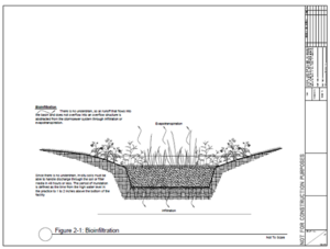
Bioinfiltration with no underdrain
Bioinfiltration is suitable for areas where significant recharge of groundwater is possible and would be beneficial. Because there is no underdrain the in-situ soils need to have a high infiltration rate to accommodate the inflow levels. The infiltration rate of the in-situ soils must be determined through proper soil testing/diagnostics. The Recommended filter media ( engineered media) depth is 2.5 feet or more to allow adequate filtration processes to occur. Most media mixes are suitable because phosphorus is not a significant concern with this practice. The Construction General Permit requires that water captured by the BMP be drawn down within 48 hours. Hydrologic soil group A and B soils are commonly suitable for bioinfiltration. Bioinfiltration is suitable for areas and land uses that are expected to generate nutrient runoff (e.g. residential and business campuses) that can be infiltrated and captured by the practice. Fresh mulch rather then aged shredded bark mulch can be used to enhance denitrification processes if nitrate leaching is a concern. Bioinfiltration is not recommended for potential stormwater hotspots. Other infiltration constraints apply to bioinfiltration practices.
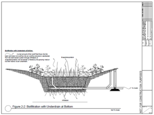
Biofiltration with underdrain at bottom
This bioretention practice is designed with an underdrain at the invert of the planting soil mix to ensure drainage at a desired rate. The practice allows for partial recharge and an impervious liner is not used. The depth is also shallow (2.5 feet) to allow high capacity flows if necessary. Siting is suitable for visually prominent or gateway locations in a community. The practice is suitable for areas and land uses that are expected to generate metals loadings (e.g. residential, business campus, or parking lots). The practice is suitable for areas with high nutrient loadings provided the media has a low phosphorus concentration or phosphorus-sorbing amendments are used (see section on filter media). This type of facility is also recommended for soils where infiltration is limited (C and D soils). Some volume reduction will be seen from evapotranspiration and partial infiltration below the underdrain.
Biofiltration with elevated underdrain
A biofiltration practice with a raised underdrain provides a storage area below the invert of the underdrain discharge pipe. This area provides a recharge zone and quantity control can also be augmented with this storage area. The storage area is equal to the void space of the material used. Since the practice utilizes both infiltration and an underdrain, considerations include those for both bioinfiltration practices and biofiltration with an underdrain at the bottom. These include an assessment of infiltration constraints and media.
Biofiltration with a liner (at bottom and or on sides)
This type of facility is recommended for areas that are known as potential stormwater hot spots (e.g. gas stations, transfer sites, and transportation depots). An important feature of this type of facility is the impervious liner designed to reduce or eliminate the possibility of groundwater contamination. The facility provides a level of treatment strictly through filtration processes that occur when the runoff moves through the soil material to the underdrain discharge point. In the event of an accidental spill, the underdrain can be blocked and the objectionable materials siphoned through an observation well and safely contained.
Biofiltration with internal water storage
The biofiltration practice with internal water storage is not commonly used in the Midwestern United States but is widely used in some places on the east coast, such as North Carolina. The use of an upturned elbow in this practice allows water to be retained within the practice, leading to increased pollutant removal, increased infiltration, and increased evapotranspiration. The practice is particularly effective at removing nitrogen through denitrification. The media should be 3 feet or more thick to allow water to be drawn down below the root zone. Underlying soils should be permeable enough to allow water stored within the practice to infiltrate.
Specific design applications for various land uses
It should be noted that the layout of the bioretention area will vary according to individual sites, and to specific site constraints such as underlying soils, existing vegetation, drainage, location of utilities, sight distances for traffic, and aesthetics. Designers are encouraged to be creative in determining how to integrate bioretention into their respective site designs. With this in mind, the following are presented as alternative options.
On-lot bioretention
Simple design that incorporates a planting bed in the low portion of the site. On-lot systems are designed to receive flows from gutters, and/or other impervious surfaces.
Parking lot islands (curbless)
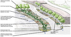
In a paved area with no curb, pre-cast car-stops or a “ribbon curb” can be installed along the pavement perimeter to protect the bioretention area. This application of bioretention should only be attempted where shallow grades allow for sheet flow conditions over level entrance areas. Water may be pooled into the parking area where parking spaces are rarely used to achieve an element of stormwater quantity control beyond the confines of the bioretention surface area (Prince George’s County, 2002).
Parking lot islands (curb-cut)
For curb-cut entrance approaches, the water is diverted into the bioretention area through the use of an inlet deflector block, which has ridges that channel the runoff into the bioretention area (Prince George’s County, 2002). Special attention to erosion control and pre-treatment should be given to the concentrated flow produced by curbcuts.
Road medians / traffic islands
A multifunctional landscape can be created by utilizing road medians and islands for bioretention. There is no minimum width recommended for traffic islands from street edge to edge. A buffer may be necessary along the outside curb perimeter to minimize the possibility of drainage seeping under the pavement section, and creating “frost heave” during winter months. Alternately, the installation of a geotextile filter fabric “curtain wall” along the perimeter of the bioretention island will accomplish the same effect.
Tree pits / tree box filters
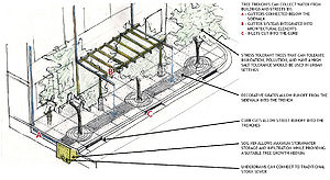
Tree pits and tree box filters afford many opportunities for bioretention. Designs vary widely from simple “tree pits”, used for local drainage interception to more formal tree box filters, which are a useful tool for highly urbanized streetscapes.
The tree pit technique provides very shallow storage areas in a “dished” mulch area around the tree or shrub. Typically, the mulched area extends to the dripline for the tree and is similar to conventional mulching practices, except that the mulch area is depressed at least 2 to 3 inches rather than mounded around the tree (Low Impact Design Center, 2005).
Tree box filters are bioretention areas installed beneath trees that can be very effective at controlling runoff, especially when distributed throughout the site. Runoff is directed to the tree box, where it is cleaned by vegetation and soil before entering a catch basin. The runoff collected in the tree-boxes helps irrigate the trees. The system consists of a container filled with a soil mixture, a mulch layer, under-drain system and a shrub or tree. Stormwater runoff drains directly from impervious surfaces through a filter media. Treated water flows out of the system through an underdrain connected to a storm drainpipe/inlet or into the surrounding soil. Tree box filters can also be used to control runoff volumes/flows by adding storage volume beneath the filter box with an outlet control device (Low Impact Design Center, 2005).
Related pages
- Bioretention terminology (including types of bioretention)
- Overview for bioretention
- Design criteria for bioretention
- Construction specifications for bioretention
- Operation and maintenance of bioretention
- Assessing the performance of bioretention
- Cost-benefit considerations for bioretention
- Calculating credits for bioretention
- Soil amendments to enhance phosphorus sorption
- Summary of permit requirements for bioretention
- Supporting material for bioretention
- External resources for bioretention
- References for bioretention
- Requirements, recommendations and information for using bioretention with no underdrain BMPs in the MIDS calculator
- Requirements, recommendations and information for using bioretention with an underdrain BMPs in the MIDS calculator
This page was last edited on 15 August 2022, at 18:50.


