Requirements, recommendations and information for using bioretention BMPs in the MIDS calculator
The MIDS calculator includes bioinfiltration (bioretention with no underdrain) and biofiltration (bioretention with an underdrain) as BMP options. For biofiltration the underdrain may be at or raised above the bottom of the BMP. Below is a summary of requirements, recommendations and other information for using the Minimal Impacts Design Standards (MIDS) calculator for bioretention BMPs. Links to MIDS pages and the MIDS calculator are included at the bottom of this page.
Contents
Bioinfiltration (Bioretention with no underdrain)
For a bioinfiltration system all water captured by the BMP is infiltrated between rain events into the underlying soil. All pollutants in the infiltrated water are captured. Water that bypasses the BMP is not treated.
Methodology
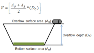
The volume of runoff water delivered to the BMP equals the performance goal (1.1 inches or user specified performance goal) times the impervious area draining to the BMP. The BMP must be sized correctly in the calculator to capture the water delivered to the BMP. Water captured by the BMP is stored above the media and below the overflow point of the BMP. The runoff volume is considered to instantaneously enter the BMP (kerplunk method). The captured volume is therefore equal to the basin depth times the average surface area of the basin ((overflow area + bottom surface area) divided by 2).
Water infiltrates at a rate equal to the saturated conductivity of the media below the ponded depth of the BMP. The most restrictive layer (lowest conductivity) within 3 feet of the bottom of the ponded water is used in the calculation. Captured water must drain within 48 hours, or 24 hours if the user specifies that as the drainage time (in the case of discharges to a trout stream).
MIDS calculator user inputs for bioinfiltration
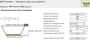
For bioinfiltration systems, the user must input the overflow surface area (the area of the BMP at the point where overflow occurs), the surface area of the bottom of the basin, the depth of the basin (the depth between the overflow surface area and the bottom surface area), the underlying soil type (HSG A, B, C, or D) and the time required for drawdown (48 hours or in the case of trout streams, 24 hours). These are discussed below.
- Overflow surface area (Ao): This is the area of the BMP at the lowest outlet point from the BMP. The user inputs this value in square feet.
- Bottom surface area (Ab): This is the surface area at the bottom of the ponded water within the BMP. This is therefore the area at the surface of the media. The user inputs this value in square feet.
- Overflow depth (Do): This is maximum depth of ponded water within the BMP (distance from the overflow elevation and top of the soil. The user inputs this this value in feet. The maximum value for this depth is 1.5 feet.
- Underlying soil - Hydrologic Soil Group: The user selects the most restrivtive soil (lowest hydraulic conductivity) within three feet of the soil/media surface in the bioinfiltration basin. there are 14 soil options for the use. These correspond with soils and infiltration rates contained inthis Manual. The user may also enter a different value. The maximum allowable infiltration rate is 1.63 inches per hour.
- Required drawdown time (hrs): This is the time the water captured by the BMP must drain into the underlying soil/media. The user may select 48 or 24 hours. The MPCA Construction Stormwater permit requires drawdown within 48 hours, but 24 hours is Highly Recommended when discharges are to a trout stream. The user will encounter an error if the water stored in the BMP cannot drawdown in the required time.
Assumptions
- The bioretention basin has been properly designed, constructed and will be properly maintained.
- Stormwater runoff entering the bioretention basin has undergone pretreatment
- The soil/media having the lowest hydraulic conductivity in the upper three feet of soil/media below the ponding area is input as the soil.
- Stormwater captured by the BMP enters the BMP instantaneously and is initially ponded within the BMP. Note this will underestimate actual infiltration since some water will enter the soil/media during a rain event, thus creating more volume for storage in the BMP.
Biofiltration with underdrain at the bottom
For a biofiltration system with the underdrain at the bottom, water is primarily lost to the underdrain. However some water infiltrates through the basin bottom and sidewalls. Evapotranspiration also occurs from vegetation in the biofiltration BMP.
Methodology
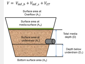
The volume of water delivered to the BMP equals the performance goal (1.1 inches or user specified performance goal) times the impervious area draining to the BMP. Unlike bioinfiltration, the volume of water netering the BMP is a function of the media depth as well as the area at the media surface and at the bottom (at the bottom of the underdrain). The volume is considered to instantaneously enter the BMP (kerplunk method). The captured volume is therefore equal to the basin depth times the average surface area of the basin ((overflow area + bottom surface area)divided by 2).
Most of the water entering the BMP will pass through the underdrain. This water provides treatment for TSS and particulate phosphorus but provides no treatment for dissolved phosphorus. A volume credit is given for water that infiltrates through the bottom of the BMP, through the sideslopes of the BMP, and for water that is evapotranspired by plants in the BMP.
For biofiltration systems (systems with an underdrain), the user must input the surface area at the overflow, the surface area at the media surface, the surface area at the underdrain, the surface area at the bottom of the system, the total media depth, and the depth below the underdrain (depth from the underdrain to the bottom of the BMP). If the underdrain is at the bottom of the system, the surface area at the underdrain will equal the bottom surface area and the depth below the underdrain will equal 0. The underlying soil and drawdown time are specified as with bioinfiltration. The user must specify the water holding capacity of the media (field capacity minus permanent wilting point). As with bioinfiltration, runoff is delivered instantaneously to the BMP. Water is lost through infiltration below the underdrain, through infiltration out the sides of the basin, and through evapotranspiration. The user can specify that an impermeable liner exists at the bottom or on the sides of the basin, in which case infiltration will not occur and the only loss of water will be through evapotranspiration.
Calculations for water lost in biofiltration systems are based on the following assumptions.
- Evapotranspiration (ET)
- average daily pan evaporation = 0.2 inches
- factor for converting pan evaporation to ET = 0.5
- duration over which ET occurs = 72 hours
- Infiltration through the bottom of the basin when an underdrain is at the bottom occurs over the drawdown time (typically 48 hours) and is a function of the infiltration rate of the soil.
- Infiltration through the bottom of the basin when the underdrain is elevated occurs over a 72 hour time period to account for drainage of water stored below the underdrain.
- Infiltration through the sides of the basin occurs over half the drawdown time (to account for decreasing contact time with the sides as the water level in the basin drops) and is a function of the soil infiltration rate.
Bioinfiltration and biofiltration BMPs can be routed to other BMPs in the MIDS calculator (other than green roofs). All other BMPs in the calculator can be routed to bioinfiltration and biofiltration BMPs. The default storm event is 1.1 inches. This value can be changed by the user. The calculator will notify the user if the default is changed.
Total suspended solids (TSS), particulate phosphorus and dissolved phosphorus loads and reductions in loading are calculated using event mean concentrations (EMCs). Default EMCs are 54.5 milligrams per liter for TSS and 0.3 milligrams per liter for total phosphorus (particulate plus dissolved). These can be changed by the user. The calculator will notify the user if the default is changed.
For bioinfiltration systems, all TSS and phosphorus captured by the BMP are reduced from the overall load delivered to the BMP. Note that more water may be delivered to the BMP than can be stored in the BMP. Excess water bypasses the BMP and receives no treatment from the BMP.
For biofiltration systems, phosphorus removal is 100 percent for all water that infiltrates through the bottom or sides of the basin. For water that is captured by an underdrain, phosphorus removal is 50 percent and TSS removal is 85 percent. It is assumed that 55 percent of all phosphorus is particulate and 45 percent is dissolved.
Requirements
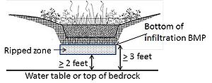
- 3 foot separation from the bottom of the bioretention system to the seasonal high water table
- Use the most restrictive infiltration rate within 3 feet of the bottom of the BMP
- Drawdown time of 24 hours when the discharge is to trout streams
- For measured infiltration rates, apply a safety factor of 2
- Pretreatment
Recommendations
- 5 acres or less for contributing area
- Maximum ponding depth of 18 inches, reduced to 6 inches if there is no site information
- Field tested infiltration rates rather than table values
Information
- Guidance on determining infiltration rates
- Information on site constraints (shallow soil, karst, etc.)
- Information on assessing BMPs
- Information on design metrics (high flow bypass, ponding depths, drawn down)
- Guidance on pretreatment
- Information on soil mixes
- Plant information, including species list that show water tolerance, potential effects of different species on infiltration rates, planting guidance
- Construction specifications
- Information on operation and maintenance of bioretention BMPs.
Links to MIDS pages
- Performance goals for new development, re-development and linear projects
- Flexible treatment options
- Ordinance goals
- MIDS calculator
Related pages
- Overview for bioretention
- Types of bioretention
- Design criteria for bioretention
- Construction specifications for bioretention
- Operation and maintenance of bioretention
- Cost-benefit considerations for bioretention
- External resources for bioretention
- References for bioretention
- Requirements, recommendations and information for using bioretention BMPs in the MIDS calculator

