Sediment control practices - Perimeter controls for disturbed areas
This page is under review through November, 2016.
Perimeter controls for disturbed areas are temporary sediment barriers that intercept and remove soil and debris from sheet flow runoff on construction sites. Removal mechanisms include ponding the runoff to allow for settling, and physically filtering sediment as it passes through a sediment barrier (e.g., silt fence, rock/soil berm, gravel bags, fiber log, etc.). Some designs (e.g., berms, ditches) use perimeter controls to collect and convey sheet flow to larger treatment areas, such as sediment traps, where sediment removal can occur through multiple processes.
Contents
Purpose and function
Perimeter controls intercept sheet flow from slopes and remove sediment and other contaminants through ponding, settling, and physical filtration, effectively preventing contaminants from leaving the site and entering surface waters. Concentrated flows within the site typically require treatment via source controls, sediment traps, settling ponds, or other methods prior to reaching the site perimeter. Ditch check dams are also used for small concentrated flows.
Although silt fences are one of the most commonly used methods of perimeter control, other perimeter control BMPs are available that can be equally or more effective depending on site conditions. Typical perimeter control methods include
- silt fence (super duty, machine sliced, hand installed, preassembled);
- ditch checks (fiber rolls/biorolls, filter/rock/compost log, etc.);
- sediment traps or berms (rock, soil, compost, etc.);
- perimeter control ditches; and
- other (sand bags, rock logs, snow berm, etc.).
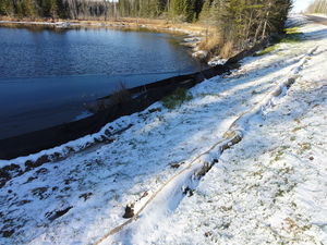
In most applications, treatment occurs at or along the perimeter control device, e.g., silt fence, rock berm, and fiber log. Other applications may involve the use of perimeter control berms or ditches to direct sheet flows to a treatment area, such as a sediment trap, sediment basin, or other BMP. Perimeter controls are generally recognized as the last line of defense in a system of erosion prevention and sediment control, and are usually placed near the downgradient borders of disturbed areas and soil stockpiles. They are also used to separate work zones from adjacent waterbodies.
Applicability
Perimeter controls are universally used to ensure that sediment and other contaminants are contained on the construction site. The wide variety of perimeter control materials, configurations, and uses make them a standard practice on nearly all construction sites where clearing, grading, excavation, or fill activities occur. The location and type of perimeter control BMPs, along with other sediment control BMPs required by the Construction Stormwater General Permit, must be identified in the site’s Stormwater Pollution Prevention Plan.
Site applicability
Perimeter controls are useful on nearly every site as part of a system of BMPs designed to prevent erosion and control sediment transport to offsite areas. The selection, installation, operation, and maintenance of a particular perimeter control or group of controls is based on site considerations: slopes, soils, site size, proximity of waterbodies, and other factors. In general, super duty silt fence and rock berms provide the most protection, and are typically indicated below steeper, longer slopes under construction during the wet season. Shorter, flatter slopes under construction during dry or frozen periods can be protected with lighter duty controls (e.g., fiber rolls). The use of silt fences as a sediment barrier is not recommended in areas of concentrated flow, such as ditches. In these cases, soil berms, silt dikes, straw wattles, excelsior logs, rock check dams, or other BMPs suitable for concentrated flow should be used.
Permit applicability
Section IV.C.2 of the 2013 MPCA Construction Stormwater General Permit states that “sediment control practices must be established on all downgradient perimeters and be located upgradient of any buffer zones” (for information on buffer zones required for temporary BMPs during construction, see Part IV.C.9; for buffer zones required as permanent BMPs, see Appendix A, Part C.3). “The perimeter sediment control practice must be in place before any upgradient land‐disturbing activities begin. These practices shall remain in place until Final Stabilization has been established”.
In addition, the permit notes that “(a) floating silt curtain placed in the water is not a sediment control BMP to satisfy perimeter control requirements in (Part IV.C.2) except when working on a shoreline and below the waterline. In those cases, a floating silt curtain can be used as a perimeter control practice if the floating silt curtain is installed as close to shore as possible. Immediately after the short term construction activity (e.g., installation of rip rap along the shoreline) in that area is complete, an upland perimeter control practice must be installed if exposed soils still drain to the surface water.”
Section IV.C.3 is also applicable to perimeter control BMPs, and states: Permittee(s) “shall re-install all sediment control practices that have been adjusted or removed to accommodate short‐term activities such as clearing or grubbing, or passage of vehicles, immediately after the short‐term activity has been completed. The Permittee(s) shall complete any short‐term activity that requires removal of sediment control practices as quickly as possible. The Permittee(s) must re‐install sediment control practices before the next precipitation event even if the short‐term activity is not complete.”
Effectiveness
Perimeter control BMPs are effective at preventing offsite sediment discharges in sheet flow when used with an appropriate upgradient system of erosion prevention and sediment control BMPs (e.g., upslope diversions, timely seeding and mulching) that minimize both the area and time of exposed soil. In some cases, full stabilization and management of disturbed upgradient areas can remove the need for extensive perimeter controls. In general, perimeter controls are high-maintenance BMPs, particularly after rain events. The following table summarizes expected performance for an array of typical water quantity and quality target constituents for properly selected, installed, and maintained perimeter controls.
Expected performance for perimeter control
Link to this table
| Water Quantity | |
|---|---|
| Flow attenuation | Little or no design benefit |
| Runoff volume reduction | Little or no design benefit |
| Water Quality | |
| Erosion prevention | Little or no design benefit |
| Sediment control | Primary design benefit |
| Nutrient loading | Secondary design benefit |
| Pollutant removal | |
| Total suspended solids | Primary design benefit |
| Total phosphorus | Secondary design benefit |
| Heavy metals | Secondary design benefit |
| Floatables | Little or no design benefit |
| Oil and grease | Little or no design benefit |
Planning considerations
Perimeter controls should be integrated into an erosion prevention and sediment control system, taking the entire site into consideration. Prior to clearing, grubbing, grading, and other earth disturbing activities, perimeter controls should be installed on all down gradient limits-of-disturbance, and upgradient of buffer zones. Integrate perimeter controls with other BMPs, such as upslope diversions of runoff around disturbed areas, minimization of disturbed areas, minimization of the length of exposure time, adequate seeding and mulching, etc. If downgradient perimeter controls become overloaded with sediment and runoff volumes, additional upgradient controls may be necessary. Perimeter controls must remain in place until final stabilization has been established.
As noted above, perimeter controls typically require a high degree of maintenance. For best results, plan and schedule project activities to minimize maintenance requirements, ideally through timely grading operations and stabilization of disturbed areas with seeding, mulching, or other ground covers. Timing of perimeter control installation may be adjusted to accommodate short term activities, such as clearing and grubbing, and passage of vehicles. Such activities must be completed as quickly as possible and the perimeter control BMPs reinstalled immediately after the activity is finished, or before the next precipitation event, whichever comes first.
Design and construction
Perimeter control design is driven by the size of the site and drainage area, slope steepness, soil type(s), proximity of waterbodies, and other factors. The design of a site’s perimeter control system should anticipate ponding that will occur upslope of the controls, and provide sufficient storage and deposition areas. Stabilized outlets are also required to prevent flows from overtopping the controls at undesired locations. The subsections below contain specific design information for the various types of materials that may be used to construct perimeter control BMPs. For all of the subsections below, the following design considerations apply.
- Specify that perimeter controls be installed downslope from disturbed areas and soil stockpiles, so that they intercept all sediment-laden flows.
- Perimeter controls are not needed upslope of disturbed areas, except when used to divert flows away from disturbed areas (i.e., diversion berms and ditches – not silt fencing).
- Where possible, leave room between the perimeter control BMP and the disturbed area for any equipment that will be used to remove sediment from or otherwise service the BMP.
- Install initial perimeter control BMPs before clearing, grubbing, grading, and other earth-disturbing activities occur.
- Keep perimeter controls in place until all upslope areas are fully stabilized.
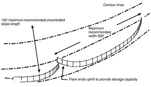
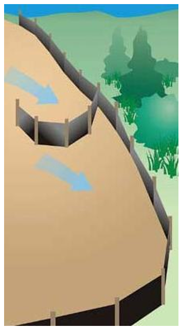
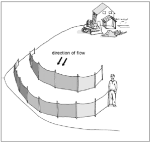
- For larger sites and/or those with steeper slopes (greater than 2 percent slopes, greater than ½ acre), perimeter controls are placed on the topographic contour, with the ends turned up to prevent bypasses.
- Where the perimeter control approach includes directing sheet flow to a separate BMP for treatment, design must include stabilization of concentrated flow areas (e.g., ditches, berms) to prevent erosion caused by moving water. Where installed adjacent to waterbodies, this approach typically involves pumping the redirected flow to an upslope location for treatment.
- Additional perimeter controls may need to be added, or controls moved to different locations on a site as conditions change.
Silt fence
Silt fencing is the perimeter control BMP used on most construction sites, and is moderately to very effective if sited, installed, and maintained properly. Silt fencing is intended to slow velocities and temporarily detain incoming runoff so that sediment is removed by settling and filtration – i.e., as muddy water passes through the fabric. Design and installation considerations for silt fencing includes the information below.
- The most common types of silt fence installations include:
- Super duty (consisting of a concrete or water filled jersey barrier with geotextile)
- Heavy duty (used where extra strength is required, such as near water bodies, on steep slopes, and in areas with unstable or highly erodible soils; typically has metal posts and is machine sliced)
- Preassembled (light-duty; posts are pre-attached to geotextile)
- Do not use in areas of concentrated flow – silt fencing is for sheet flow only.
- For predominantly sandy soils, fabrics with Standard Sieve opening sizes of 10 to 30 are acceptable. For mostly silty soils, use fabric with 30 to 60 Standard Sieve openings. For clayey soils, specify silt fence fabric with Standard Sieve size openings of 60 to 100 or higher. Use the higher range values (i.e., smaller openings), for silt fences along surface waters and buffer areas.
- Silt fences should be installed on the contour (as opposed to up and down a hill).
- Since silt fence is not designed to withstand high water levels, locate them so that only shallow pools can form – i.e., no more than half the height of the silt fence.
- Spacing of wood or metal posts should not exceed 6 feet and should be installed on the downhill side of the fabric.
- Silt fence serves no function along ridges or near drainage divides where there is little movement of water. Confining or diverting runoff unnecessarily with a sediment fence may create erosion and sedimentation problems that would not otherwise occur.
The following describes the components and installation of the silt fence:
- Anchoring of the silt fence is critical. The bottom 6 to 12 inches of the fabric must be buried and compacted to prevent bypasses.
- Burial of the bottom of the fabric can be via trench and backfill, or via the slicing method.
- Posts can be 2x2 inch hardwood, metal T-posts, or round metal posts. Steel posts are used typically for heavy duty applications, while standard applications may use wooden posts.
- Posts should be driven at least 1.5 to 2 feet into the ground, to support runoff and sediment loads.
- Use J-hooks to intercept and trap flows that may run along silt fence sections.
- Low fence line corners and dips should be reinforced with rock or other berms/checks.
- Silt fence ends should be turned upslope to capture runoff and prevent bypasses.
- Lightly pull fabric taut during installation – avoid excessive sagging between posts.
- Fabric can be attached to posts with staples, plastic ties, wire, or clips.
Fiber Logs/Rolls
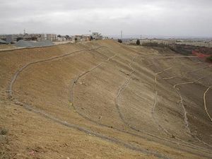
Fiber logs, fiber rolls, biorolls, or wattles fabricated from a variety of materials (e.g., straw, wood fiber, compost, coconut, etc.) can perform effectively as perimeter control BMPs for relatively flatter sites or smaller drainage areas. They are also effective when used with mulch or erosion control blankets on steeper slopes to break up slope lengths, intercept and spread out downslope flows, promote vegetative growth, and generally prevent slope erosion.
Design guidelines for using fiber logs as perimeter controls include:
- Do not use for perimeter control below slopes longer than 30 feet and steeper than 15 percent.
- When used for perimeter control, use 20 inch diameter logs where slopes are 10 to 15 percent, 10 inch diameter logs for slopes 5 to 10 percent, and 8 inch diameter logs for flatter slopes.
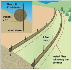
- On slopes, install on the contour, with ends turned upslope slightly to deter bypasses.
- If installing on bare soil, prepare a smooth, rounded trench with a depth of ¼ the log diameter.
- Must be staked down. When staking down, ensure good soil contact for the full length of the fiber log.
- Where used on slopes, space 10 feet apart for 1H:1V slopes, 20 feet apart for 2H:1V slopes, 30 feet apart for 3H:1V slopes, and 40 feet apart for 4H:1V or flatter slopes.
- Use stakes that are 16 inches longer than the diameter of the fiber log for soft soils, and 10 inches longer than the fiber log diameter in hard or rocky soils. Space stakes no more than 3 to 4 feet apart; shorten stake spacing on steeper slopes
Rock and Other Berms
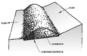
Perimeter control berms consisting of stabilized soil, rock, rock bags, mulch, compost, grubbed roots and brush, and other material can also serve to reduce sediment discharges offsite, through ponding, filtration, or redirection of runoff to a sediment trap or other treatment unit. These systems are a very efficient method for sediment removal, but may require frequent maintenance as they are prone to clogging from mud and soil. In addition, installation may be labor intensive, they are easily damaged by equipment, and removal can be difficult. Design considerations include the general guidelines listed at the beginning of this section, as well as those listed below:
- As with other perimeter controls, rock and other berms are typically installed on the contour, with the ends turned upslope to prevent bypasses.
- Soil berms (i.e., linear stockpiles) used to redirect sheet flows to treatment areas (e.g., sediment traps, rock berm or check) should be stabilized immediately with vegetation, erosion control blankets, or other means to prevent the berm from eroding and becoming a source of sediment runoff. Temporary flow checks and an outlet flow dissipater may be needed, depending on the slope.
- Rock or gravel bags can be used as a sheet flow diversion berm or as a ponding/filtration perimeter control. Bags should not be filled more than two-thirds, so that they create a solid berm without large spaces or gaps between the bags.
- Compost berms and shredded wood mulch berms may be used in flatter areas where other perimeter controls are not feasible. Compost berms must meet MnDOT Specification 3890 Grade 2. Compost and shredded wood mulch berms should be at least 2.5 feet wide and 1 foot tall.
Perimeter control ditches
Perimeter control ditches function like soil berms – they redirect downslope sheet flow from the disturbed area perimeter to a sediment trap, settling pond, rock berm, or other treatment unit designed to settle or filter soil from site runoff. Design considerations include:
- All ditches must be stabilized immediately after construction. Seeding rates and the use of mulch or rolled erosion control products will be determined by the ditch slope and other site-specific factors.
- Long, steep ditches may need temporary ditch checks to prevent erosion and down-cutting.
- Where using a ditch or berm to redirect site runoff from the perimeter to a separate treatment unit (e.g., sediment trap or pond) and the disturbed area perimeter is within or adjacent to the protective buffer of a surface water body, consider siting the treatment unit at an upslope location.
Cold Weather considerations
Permit requirements specify that all construction sites must remain in compliance throughout winter, even if no construction is occurring. Properly functioning sediment controls must remain in place during minor thaws and during the large spring snowmelt to prevent transport of sediment to surface waters. The best way to ensure proper functioning of perimeter controls throughout winter is to have all sediment controls installed prior to the first freeze. For winter construction, materials such as compost berms, logs and rolls, fiber rolls, rock bags, and rock filters can be installed over snow cover to provide new sediment control. Snow berms may also be used for projects that will be complete before snowmelt. All BMPs must be inspected and maintained immediately following intermittent snow melt or rainfall that occurs in winter months.
Standards and specifications
MnDOT Standard Plan 5-297.405 provides standard detail for perimeter control BMPs utilized for temporary sediment control (effective date: 8/6/2014). BMPs covered include “Flotation Silt Curtain”, “Sediment Control Logs”, “Filter Berms”, “Bale Barriers”, and several “Silt Fence” plans (including Types TB, HI, MS, and PA).
The MnDOT Standard Specifications for Construction (2016 edition) outline specific requirements for various types of perimeter control BMPs, including selection and materials specifications. Applicable specifications include 2573 (Storm Water Management), 3149 (Granular Material), 3874 (Filter Berm), 3882 (Mulch Material), 3886 (Silt Fence), 3887 (Flotation Silt Curtain), 3890 (Compost), 3893 (Sandbags), and 3897 (Sediment Control Log), see http://www.dot.state.mn.us/pre-letting/spec/
Inspection
For all perimeter control BMPs, initial inspections should ensure that controls are intercepting all upslope runoff from disturbed areas. Check upslope areas to determine if there are opportunities to reduce the volume of runoff being handled by perimeter controls, reduce the amount of sediment in the runoff (i.e., by installing diversions above the disturbed area), or immediately stabilize idle bare areas and/or portions of the site that are at final grade. Where perimeter controls redirect flows to sediment traps, ponds, or other treatment BMPs, ensure that berms/ditches are stable, flow paths are unobscured, and that the treatment BMP is able to handle inflows appropriately and are functioning properly. If it is determined through inspection that the selected perimeter control BMPs are ineffective, they must be upgraded to a method that is effective at keeping sediment on the site.
MnDOT’s workmanship and rework schedule (2016; version under development at the time of manual update) identifies common deficiencies for various types of perimeter control BMPs and corrective actions for these deficiencies. Once complete, the full, final version of this table will replace Table 2573-1 in MnDOT Standard Specifications for Construction (2016 edition).
Temporary Sediment Control - Corrective Actions
Link to this table
| Item | Corrective Action Required if | Corrective Action |
|---|---|---|
| Silt fence |
|
|
| Bale barriers |
|
|
| Filter berms |
|
|
| Floating silt curtain |
|
|
| Perimeter controls |
|
|
| Sediment control logs |
|
|
| Sandbag barrier |
|
|
The subsections below provide additional inspection guidelines for each of the BMPs addressed in the section above.
Silt fence
- During installation, make sure support posts are on the downhill side of the fabric.
- Inspect silt fences at least once a week and after each rainfall, as required by permits, and make required repairs immediately.
- Verify posts are correctly spaced.
- After installation, tug on the top of the fabric between posts to ensure that it is embedded tightly.
- Make sure fabric is securely attached to the posts, without excessive sagging.
- Ensure geotextile overlap is used on heavy duty type fence.
- Ensure soil is compacted (not turned over/loosened) for machine-sliced fence.
- After a rain, check silt fences for bypasses below or around the ends of each silt fence section.
- Note and record blowouts, sections where the fence is down, etc.
- Note the condition of support posts along each section of silt fence.
- Observe and record the amount of sediment deposited on the upslope side of the silt fence.
Fiber logs
- After a rain, check for bypasses under the fiber logs and at the ends of each row.
- Note the physical integrity of the logs, and document any significant deterioration found.
- Check the stakes to make sure they are still holding the logs securely in place.
Rock and other berms
- Make sure berms retain their initial configuration and ponding/filtration/flow function.
- Look for scouring downslope of berms where ponded overflows occur.
- Check berms and note areas where runoff has blown out or bypassed bermed areas.
- Look for washouts, undercutting (e.g., animal burrows), and end bypasses along berms.
Perimeter control ditches
- Observe the flow perimeter of ditches and note any vertical or horizontal scour erosion.
- Look for scour and offsite sediment discharges where ditches overflow during heavy rains.
Maintenance
The maintenance guidelines below respond directly to the inspection findings that result from observing field conditions listed in the previous section. For best results, complete maintenance tasks immediately, before conditions worsen and consume more time and resources to resolve. Below are some key requirements from the 2013 MPCA Construction Stormwater General Permit:
- “If the down gradient sediment controls are overloaded (based on frequent failure or excessive maintenance requirement), the Permittee(s) must install additional upgradient sediment control practices or redundant BMPs to eliminate the overloading, and the SWPPP must be amended to identify these additional practices.”
- The permittee is required to “re‐install all sediment control practices that have been adjusted or removed to accommodate short‐term activities such as clearing or grubbing, or passage of vehicles, immediately after the short‐term activity has been completed.” Permittees must “complete any short‐term activity that requires removal of sediment control practices as quickly as possible,” and “must re‐install sediment control practices before the next precipitation event even if the short‐term activity is not complete.”
- “All perimeter control devices must be repaired, replaced, or supplemented when they become nonfunctional or the sediment reaches one‐half (1/2) of the height of the device. These repairs must be made by the end of the next business day after discovery, or thereafter as soon as field conditions allow access.”
Other maintenance guidelines include:
- Use J-hooks along silt fences, berms, and other structures to break up long flow paths, reduce flow velocities, and trap sediment before it reaches downgradient locations.
- Add more/longer stakes where fiber rolls become dislodged by runoff.
- Repair or replace perimeter controls found to be non-functional, due to severe weather conditions, age, extended use, damage, or other causes.
- Use rock berms along dips and in low corners of silt fences, fiber logs, and other BMPs if blowouts and bypasses occur frequently in these locations.
- Where repeated failures occur, install additional upgradient erosion prevention and/or sediment control practices or redundant BMPs to eliminate the problem (see above).
- Repair or replace ineffective fabric and fiber rolls due to collapse, tearing, decomposition, etc. within 24 hours of discovery.
- When all areas above the perimeter control BMP(s) have been stabilized, the temporary BMP(s) (e.g., silt fences, temporary berms, etc.) must be removed. (Note: Fiber logs are typically left in place on slopes.)
- After removing temporary BMPs, collect and dispose of the accumulated sediment, and fill and compact holes, trenches, depressions, or any other ground disturbance to blend with the surrounding landscape. Stabilize the area with seed, mulch, sod, or other BMP.
Costs
The following table summarizes estimated BMP costs based on MnDOT data summarizing average bid prices for awarded projects in 2014.
Perimeter controls for disturbed areas - Average Bid Prices
Link to this table
| Bid Item | Item Description | Units | Average Price |
|---|---|---|---|
| 2573.501/00010 | Bale Barrier | LF | $4.97 |
| 2573.502/00010 | Silt Fence, Type HI | LF | $2.58 |
| 2573.502/00020 | Silt Fence, Type PA | LF | $7.00 |
| 2573.502/00030 | Silt Fence, Type SD | LF | $19.87 |
| 2573.502/00040 | Silt Fence, Type MS | LF | $1.99 |
| 2573.502/00050 | Silt Fence, Type TB | LF | $10.24 |
| 2573.504/00010 | Sandbag Barrier | SF | $10.55 |
| 2573.505/00010 | Flotation Silt Curtain Type Still Water | LF | $14.99 |
| 2573.505/00020 | Flotation Silt Curtain Type Moving Water | LF | $39.57 |
| 2573.515/00013 | Filter Berm Type 3 | LF | $54.49 |
| 2573.515/00015 | Filter Berm Type 5 | LF | $22.95 |
| 2573.533/00011 | Sediment Control Log Type Straw | LF | $2.90 |
| 2573.533/00012 | Sediment Control Log Type Wood Fiber | LF | $4.29 |
| 2573.533/00013 | Sediment Control Log Type Coir | LF | $13.25 |
| 2573.533/00015 | Sediment Control Log Type Compost | LF | $2.58 |
| 2573.533/00016 | Sediment Control Log Type Rock | LF | $5.00 |
| 2573.533/00017 | Sediment Control Log Type Blanket System | LF | $2.52 |
LF=linear foot; SF=square foot
Reference Materials
Except where more stringent requirements are presented in this guidance, perimeter controls shall comply with MnDOT and other state requirements. Primary design references include:
- MnDOT Erosion Control Handbook II
- Minnesota Urban Small Sites Best Management Practice Manual (Silt Fences)
- 2013 Minnesota NPDES/SDS Construction Stormwater General Permit
- MnDOT Standard Specifications for Construction (2016 Edition)
- MnDOT Standard Drawings for use in Construction Plans
The following is a list of additional resources that are not specific to Minnesota:
- Clean Water Services Erosion Prevention and Sediment Control Manual (4.3.4 Filter Berm, 4.3.10 Sediment Fence)
- North Carolina Erosion and Sediment Control Planning and Design Manual (6.62 Sediment Fence (Silt Fence), 6.66 Compost Sock)
- Tennessee Department of Environment and Conservation (TDEC) Erosion and Sediment Control Handbook (7.34 Silt fence)
- Virginia Erosion and Sediment Control Handbook (3.05 Silt Fence, 3.06 Brush Barrier)
- [Clark County Washington Stormwater Manual (BMP C232: Gravel Filter Berm, BMP C233: Silt Fence)
- Best Management Practices (BMPs) for Controlling Erosion, Sediment, and Pollutant Runoff from Construction Sites. University of Kentucky, 2009.
- Delaware Erosion and Sediment Control Handbook. 2003
