m
Line 1: Line 1:
 
{{alert|This page is an edit and testing page use by the wiki authors.  It is not a content page for the Manual. Information on this page may not be accurate and should not be used as guidance in managing stormwater.|alert-danger}}
 
{{alert|This page is an edit and testing page use by the wiki authors.  It is not a content page for the Manual. Information on this page may not be accurate and should not be used as guidance in managing stormwater.|alert-danger}}
  
==a==
 
 
[[Raj test page]]
 
[[Raj test page]]
  
<div style="float:right">
+
=[[Green Stormwater Infrastructure (GSI) and sustainable stormwater management]]=
<table class="infobox" style="border:3px; border-style:solid; border-color:#FF0000; text-align: left; width: 300px; font-size: 100%">
+
Green infrastructure encompass a wide array of practices, including stormwater management. Water management using green infrastructure practices mimics the natural water cycle. Examples of green infrastructure practices include planting trees, restoring wetlands, enhancing biodiversity, and restoring floodplains. Green infrastructure incorporates both the natural environment and engineered systems to provide clean water, conserve ecosystem values and functions, and provide a wide array of benefits to people and wildlife. Green infrastructure can be applied on different scales, from the house or building level, to the broader landscape level. On the local level, green infrastructure practices include rain gardens, permeable pavements, green roofs, infiltration planters, trees and tree boxes, and rainwater harvesting systems. At the largest scale, the preservation and restoration of natural landscapes (such as forests, floodplains and wetlands) are critical components of green infrastructure.
<tr>
 
<th><center><font size=3>'''Page summary'''</font size></center></th>
 
</tr>
 
<tr>
 
<td>This page provides guidance related to assessing the total suspended sediment (TSS) and total phosphorus (TP) removal efficiency of MS4 (Municipal Separate Storm Sewer System) permittee owned/operated ponds constructed and used for the collection and treatment of stormwater. Four (4) evaluation strategies are discussed.
 
#'''Evaluation of pond design criteria'''. This method evaluates pond size criteria against pond design standards to determine if the pond is properly sized to achieve desired water quality performance. The method requires low effort and has low accuracy.
 
#'''Pond inspection/assessment'''. This method relies on routine inspection and assessment to ensure the pond is being maintained at a level that achieves the desired water quality performance. This method requires a medium to high level of effort. The method does not inherently provide an estimate of accuracy.
 
#'''Stormwater pond pollutant removal modeling'''. This method utilizes empirical or physical water quality models to estimate water quality performance of a pond. It requires low to medium effort and provides medium accuracy.  
 
#'''Stormwater pond water quality monitoring'''. This method utilizes water quality monitoring of pond inflow and outflow to determine water quality function of the pond. It requires a high level of effort and provides high accuracy.
 
  
Sections on this page provide descriptions of these methods and case studies.
+
Stormwater management using green infrastructure practices involves keeping and using water close to its point of origin (i.e. keeping the raindrop where it falls). Practices include those local practices mentioned above - rain gardens, permeable pavements, green roofs, infiltration planters, trees and tree boxes, and rainwater harvesting systems. Because there multiple benefits of these practices, in addition to stormwater management, the manual includes a variety of topics related to green infrastructure as illustrated below.
</td>
 
</tr>
 
</table>
 
</div>
 
  
==Evaluation of MPCA Stormwater Pond Design Criteria==
+
{{alert|Throughout this manual, these green alert boxes identify a stormwater practice that is considered a green infrastructure practice.|alert-success}}
The MPCA Minnesota Stormwater Manual contains detailed design criteria for many water quality best management practices (BMPs), including constructed stormwater ponds. In addition to outlining construction stormwater pond requirements stipulated by the MPCA Construction General Permit (CGP), the Minnesota Stormwater Manual’s Design Criteria for Stormwater Ponds contains guidance and recommendations related to many aspects of stormwater pond design and construction, from grading and site layout, to overflow spillway design and development of a landscaping plan. Although guidance within the Design Criteria for Stormwater Ponds is primarily focused on requirements related to construction of design of stormwater ponds for new development, elements within the guidance related to sizing of the pond permanent pool volume and live storage water quality volume can be used to evaluate (a) the impact of sedimentation over time and (b) the impact of development and changing land use over time on the water quality performance of existing stormwater ponds. The following subsections outline how design criteria can be used to evaluate the water quality treatment efficiency of existing stormwater ponds and how design criteria can be used to estimate pollutant load reduction.
 
  
===Estimating Water Quality Performance of Existing Stormwater Ponds===
+
==Green Stormwater Infrastructure and sustainable stormwater management==
[[File:Constructed pond 1 for credit page.jpg|thumb|200px|alt=schematic of constructed pond/wetland|<font size=3>Constructed ponds and constructed wetlands are examples of sedimentation practices. (Source: CDM Smith).</font size>]]
+
*[[Overview to Green Stormwater Infrastructure]]
 +
*[[Overview to sustainable stormwater management]]
 +
*[[Planning Green Stormwater Infrastructure projects and practices]]
 +
*[[Designing Green Stormwater Infrastructure projects and practices]]
 +
*[[Maintaining and assessing Green Stormwater Infrastructure projects and practices]]
  
As discussed in Section 2.0, the Minnesota Stormwater Manual’s Design Criteria for Stormwater Ponds
+
==Green Stormwater Infrastructure Best Management Practices==
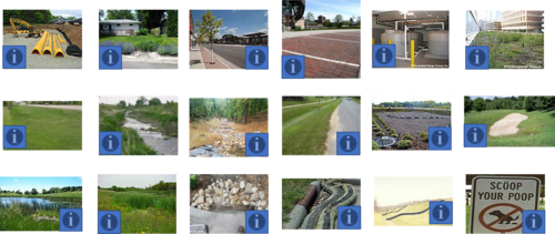
contains guidance and requirements related to the sizing of pond permanent pool volume (Vpp) and live storage water quality volume (Vwq). As defined by the Minnesota Stormwater Manual, the permanent pool (aka, “dead storage”) is the volume of water below the pond outlet, and the water quality volume (aka, “live storage”) is the storage volume between the pond outlet and the pond overflow elevation as
+
<imagemap>
shown in Figure 1.
+
Image:Stormwater BMPs.png|500px|thumb|alt=imagemap for stormwater BMPs|Stormwater Best Management Practices. Mouse hover over an '''i''' box to read a description of the practice, or click on an '''i''' box to go to a page on the practice.
 
+
circle 30 125 30 [[Infiltration|Infiltration basins, infiltration trenches, dry wells, and underground infiltration systems capture and temporarily store stormwater before allowing it to infiltrate into the soil. As the stormwater penetrates the underlying soil, chemical, biological and physical processes remove pollutants and delay peak stormwater flows.]]
The Minnesota Stormwater Manual’s Design Criteria for Stormwater Ponds outlines minimum requirements for permanent pool volume (Vpp) and water quality volume (Vwq) as outlined by the CGP. Narrative descriptions and resulting equations used to evaluate minimum volume required are outlined below.
+
circle 270 125 30 [[Bioretention|Bioretention (rain garden) is a terrestrial-based (up-land as opposed to wetland) water quality and water quantity control process. Bioretention employs a simplistic, site-integrated design that provides opportunity for runoff infiltration, filtration, storage, and water uptake by vegetation.]]
 
+
circle 600 125 30 [[Trees|Tree trenches and tree boxes (collectively called tree BMP(s)), the most commonly implemented tree BMPs, can be incorporated anywhere in the stormwater treatment train but are most often located in upland areas of the treatment train. The strategic distribution of tree BMPs help control runoff close to the source where it is generated. Tree BMPs can mimic certain physical, chemical, and biological processes that occur in the natural environment.]]
The Required minimum permanent pool volume, or dead storage (Vpp), below the outlet elevation), is 1800
+
circle 690 150 30 [[Permeable pavement|Permeable pavements allow stormwater runoff to filter through surface voids into an underlying stone reservoir for temporary storage and/or infiltration. The most commonly used permeable pavement surfaces are pervious concrete, porous asphalt, and permeable interlocking concrete pavers (PICP). Permeable pavements have been used for areas with light traffic at commercial and residential sites to replace traditional impervious surfaces in low-speed roads, alleys, parking lots, driveways, sidewalks, plazas, and patios.]]
cubic feet of storage below the outlet pipe for each acre that drains to the pond
+
circle 920 125 30 [[Stormwater and rainwater harvest and use/reuse|A stormwater harvesting and use system is a constructed system that captures and retains stormwater for beneficial use at a different time or place than when or where the stormwater was generated. A stormwater harvesting and use system potentially has four components: collection system (which could include the catchment area and stormwater infrastructure such as curb, gutters, and stormsewers), storage unit (such as a cistern or pond) treatment system: pre and post (that removes solids, pollutants and microorganisms, including any necessary control systems), if needed, and the distribution system (such as pumps, pipes, and control systems).]]
 
+
circle 1130 125 30 [[Green roofs|Green roofs consist of a series of layers that create an environment suitable for plant growth without damaging the underlying roof system. Green roofs create green space for public benefit, energy efficiency, and stormwater retention/ detention. Green roofs occur at the beginning of stormwater treatment trains. Green roofs provide filtering of suspended solids and pollutants associated with those solids, although total suspended solid (TSS) concentrations from traditional roofs are generally low. Green roofs provide both volume and rate control, thus decreasing the stormwater volume being delivered to downstream Best Management Practices (BMPs).]]
<math>V_{pp} = 1800A</math>
+
circle 30 325 30 [[Dry swale (Grass swale)|Dry swales, sometimes called grass swales, are similar to bioretention cells but are configured as shallow, linear channels. They typically have vegetative cover such as turf or native perennial grasses. Dry swales may be constructed as filtration or infiltration practices, depending on soils. If soils are highly permeable (A or B soils), runoff infiltrates into underlying soils. In less permeable soils, runoff is treated by engineered soil media and flows into an underdrain, which conveys treated runoff back to the conveyance system further downstream. Check dams incorporated into the swale design allow water to pool up and infiltrate into the underlying soil or engineered media, thus increasing the volume of water treated.]]
 
+
circle 270 325 30 [[Wet swale (wetland channel)|Wet swales occur when the water table is located very close to the surface or water does not readily drain out of the swale. A wet swale acts as a very long and linear shallow biofiltration or linear wetland treatment system. Wet swales do not provide volume reduction and have limited treatment capability. Incorporation of check dams into the design allows treatment of a portion or all of the water quality volume within a series of cells created by the check dams. Wet swales planted with emergent wetland plant species provide improved pollutant removal. Wet swales may be used as pretreatment practices. Wet swales are commonly used for drainage areas less than 5 acres in size.]]
where
+
circle 600 325 30 [[High-gradient stormwater step-pool swale|Stormwater step pools address higher energy flows due to more dramatic slopes than dry or wet swales. Using a series of pools, riffle grade control, native vegetation and a sand seepage filter bed, flow velocities are reduced, treated, and, where applicable, infiltrated. The physical characteristics of the stormwater step pools are similar to Rosgen A or B stream classification types, where “bedform occurs as a step/pool, cascading channel which often stores large amounts of sediment in the pools associated with debris dams”. Stormwater step pools are designed with a wide variety of native plant species depending on the hydraulic conditions and expected post-flow soil moisture at any given point within the stormwater step pool.]]
:A = the drainage area of the stormwater pond (acres)
+
circle 820 325 30 [[Vegetated filter strips|Vegetated filter strips are designed to remove solids from stormwater runoff. The vegetation can consist of natural and established vegetation communities and can range from turf grass to woody species with native grasses and shrubs. Because of the range of suitable vegetation communities, vegetated filter strips can be easily incorporated into landscaping plans; in doing so, they can accent adjacent natural areas or provide visual buffers within developed areas. They are best suited for treating runoff from roads, parking lots and roof downspouts. Their primary function is to slow runoff velocities and allow sediment in the runoff to settle or be filtered by the vegetation. By slowing runoff velocities, they help to attenuate flow and create a longer time of concentration. Filter strips do not significantly reduce runoff volume, but there are minor losses due to infiltration and depression storage. Filter strips are most effective if they receive sheet flow and the flow remains uniformly distributed across the filter strip.]]
 
+
circle 1040 325 30 [[Iron enhanced sand filter (Minnesota Filter)|Iron-enhanced sand filters are filtration Best Management Practices (BMPs) that incorporate filtration media mixed with iron. The iron removes several dissolved constituents, including phosphate, from stormwater. Iron-enhanced sand filters may be particularly useful for achieving low phosphorus levels needed to improve nutrient impaired waters. Iron-enhanced sand filters could potentially include a wide range of filtration BMPs with the addition of iron; however, iron is not appropriate for all filtration practices due to the potential for iron loss or plugging in low oxygen or persistently inundated filtration practices.]]
or
+
circle 1130 325 30 [[Filtration|Sand (media) filters have widespread applicability and are suitable for all land uses, as long as the contributing drainage areas are limited (e.g., typically less than 5 acres). Sand filters are not as aesthetically appealing as bioretention, which makes them more appropriate for commercial or light industrial land uses or in locations that will not receive significant public exposure. Sand filters are particularly well suited for sites with high percentages of impervious cover (e.g., greater than 50 percent). Sand filters can be installed underground to prevent the consumption of valuable land space (often an important retrofit or redevelopment consideration).]]
 
+
circle 170 525 30 [[Stormwater ponds|Stormwater ponds are typically installed as an end-of-pipe BMP at the downstream end of the treatment train. Stormwater pond size and outflow regulation requirements can be significantly reduced with the use of additional upstream BMPs. However, due to their size and versatility, stormwater ponds are often the only management practice employed at a site and therefore must be designed to provide adequate water quality and water quantity treatment for all regulated storms.]]
<math>V_{pp} = 0.0417 A </math>
+
circle 265 525 30 [[Stormwater wetlands|Stormwater wetlands are similar in design to stormwater ponds and mainly differ by their variety of water depths and associated vegetative complex. They require slightly more surface area than stormwater ponds for the same contributing drainage area. Stormwater wetlands are constructed stormwater management practices, not natural wetlands. Like ponds, they can contain a permanent pool and temporary storage for water quality control and runoff quantity control. Wetlands are widely applicable stormwater treatment practices that provide both water quality treatment and water quantity control. Stormwater wetlands are best suited for drainage areas of at least 10 acres. When designed and maintained properly, stormwater wetlands can be an important aesthetic feature of a site.]]
 
+
circle 600 525 30 [[Pretreatment|Pretreatment practices are installed immediately preceding one or more structural stormwater BMPs. Pretreatment reduces maintenance and prolongs the lifespan of structural stormwater BMPs by removing trash, debris, organic materials, coarse sediments, and associated pollutants prior to entering structural stormwater BMPs. Implementing pretreatment devices also improves aesthetics by capturing debris in focused or hidden areas.]]
where
+
circle 820 510 30 [[Sediment control practices|Sediment control practices are designed to prevent or minimize loss of eroded soil at a site. Typical sediment control practices focus on 1) physical filtration of sediment by trapping soil particles as water passes through a silt fence, drop inlet screen, fiber roll, etc., 2)settling processes, that allow sediment to fall out of flows that are slowed and temporarily impounded in ponds, traps, or in small pools created by berms, silt fencing, inlet protection dikes, check dams, etc.]]
:A = the drainage area of the stormwater pond (square feet)
+
circle 1040 500 30 [[Erosion prevention practices|Erosion prevention practices include 1) planning approaches that minimize the size of the bare soil area and the length of time disturbed areas are exposed to the elements especially for long, steep slopes and easily erodible soils, 2) diverting or otherwise controlling the location and volume of run-on flows to the site from adjacent areas, 3)keeping concentrated flows in ditches stabilized with vegetation, rock, or other material, and 4)covering bare soil with vegetation, mulch, erosion control blankets, turf reinforcement mats, gravel, rock, plastic sheeting, soil binder chemicals, etc.]]
 
+
circle 1255 525 30 [[Pollution prevention|Pollution prevention (P2) is a “front-end” method to decrease costs, risks, and environmental concerns. In contrast to managing pollution after it is created, P2 reduces or eliminates waste and pollution at its source. P2 includes a variety of residential, municipal, and industrial practices.]]
The equations and definitions, above, were created for designing and constructing a stormwater pond to treat runoff from new development. Existing stormwater ponds may have larger Vpp than the minimum required by the CGP, or may have larger or smaller Vwq than required. To estimate the water quality performance of existing stormwater ponds, methodology outlined in the Minnesota Stormwater Manual’s MIDS Calculator documentation for stormwater ponds requires the user to evaluate the tributary area to the pond and volume dimension of the pond to determine the “design level” (e.g., Design Level 2) of the pond, and recommends assumed pollutant removal efficiency values based on the design level (e.g., 84% TSS removal for Design Level 2). Criteria for each MIDS stormwater pond design level are summarized in Table 2.
+
</imagemap>
 
 
{{:MIDS Calculator stormwater pond design level criteria related to pond volume}}


Steps for summarizing the estimating water quality performance of existing stormwater ponds using methodology outlined in the Minnesota Stormwater Manual’s Design Criteria for Stormwater Ponds and MIDS Calculator documentation for stormwater ponds are outlined, below.


1) Determine the permanent pool volume (Vpp) of the pond – the VPP can be determined through a number of sources, including record drawings, as-builts, and bathymetric survey. Note: before using record drawing or as-built data, a pond assessment (Section 3.0) should be conducted to determine the extent to which sedimentation has reduced the Vpp. If estimating volume from bathymetric contour data, the following equation can be used to calculate volume between any two bathymetric contours. The total bathymetric volume can then be calculated by summing the volume between all available bathymetric contours


<math> 𝑽_{𝟏−𝟐} = (𝑨_𝟏 + 𝑨_𝟐)/2 × (𝑬_𝟐 − 𝑬_𝟏) </math>


Where,
 
:V<sub>1-2</sub> = the volume between contours 1 and 2;
 
:A<sub>1</sub> and A<sub>2</sub> = the area of contours 1 and 2, respectively; and
 
:E<sub>1</sub> and E<sub>2</sub> = the elevation of contours 1 and 2, respectively


After calculating the volume between each bathymetric contour, the total bathymetric volume can be calculated by summing the volume calculated between each set of contours


<math> ∑ 𝑽_𝒊 = (𝑨_{𝒏+𝟏} + 𝑨_n)/𝟐 × (𝑬_{𝒏+𝟏} − 𝑬_𝒏) </math>


If only the area at the bottom of the pond (A<sub>pp</sub>) and the area at the permanent pool of the pond (A<sub>bot</sub>) is known, the bathymetric volume can be calculated using the simplified equation


<math> ∑ 𝑽_{bathymetric} = (𝑨_{pp} + 𝑨_{bot})/𝟐 × (𝑬_{pp} − 𝑬_{bot}) </math>


Where
 
:V<sub>bathymetric</sub> = bathymetric volume;
 
:A<sub>pp</sub> = area at the permanent pool of the pond;
 
:A<sub>bot</sub> = area at the bottom of the pond;
 
:E<sub>pp</sub> = elevation at the bottom of the pond; and
 
:E<sub>bot</sub> = elevation of the bottom of the pond.


2) Determine the water quality volume (Vwq) of the pond – as shown in Figure 1, the Vwq is the volume between the ponds permanent pool and the natural or designed overflow elevation. The Vwq can be determined through a number of sources, including record drawings, as-builts, survey data, and surface LiDAR data. A rough estimate of Vwq can be calculated by determining the permanent pool area and the area at the natural or designed overflow elevations. Equation 3, above, can then be used using these two elevations and areas.


3) Evaluate the Vpp of the pond – determine the CGP required Vpp based on the total drainage area to the stormwater pond using Equation 1, above (i.e., 1,800 ft3 per acre of drainage area). If the Vpp is greater than 1,800 ft3, proceed to step 4. If the Vpp of the pond is less than 1,800 ft3 per acre of drainage area, guidance within the Minnesota Stormwater Manual suggests that the pond should not be included in site pollutant removal calculations, as the pond is unlikely to provide adequate treatment. To estimate the water quality performance of a stormwater pond not meeting minimum Vpp requirements, calculations in the following steps can proceed by using only the area for which the
 
Vpp is sized to adequately treat (i.e., Vpp ÷ 1,800 ft3 /acre = treated area (acres)). The remaining portion of the total drainage area to the pond would then be assumed to bypass (i.e., 0% treatment). Alternatively, water quality performance of undersized stormwater ponds can be evaluated through modeling (Section 4.0) or monitoring (Section 5.0).


4) Evaluate the tributary impervious area to the pond – for small sites (e.g., developments less than two acres, etc.), impervious area can be determined through manual evaluation of site impervious cover from record drawings or site plans. For larger drainage stormwater ponds with larger drainage areas (e.g. regional stormwater ponds with drainage areas greater than five acres), land use datasets can be used to estimate total impervious area within the ponds drainage area. The Minnesota Geospatial Information Office (MnGeo) maintains a database of current and historic land use which can be used to evaluate land use and estimate impervious area. Additionally, the University of Minnesota (UMN) provides land cover and impervious data at varying resolution statewide and for specific regions throughout Minnesota (e.g. Twin Cities Metro, Duluth, Rochester, etc.).


5) Determine the impervious area treatment depth in the pond Vwq using the pond Vwq (Step 2) tributary impervious area (step 4), calculate the impervious area treatment depth using Equation 4, below. Note: Equation 4 is the same as Equation 2 but rearranged to calculate the impervious area treatment depth provided by the pond Vwq.


<math> 𝑫_𝒊 = 𝑽_𝒘 𝑨_𝒊 × 𝟏_{𝒊𝒇} </math>


Where
 
:Dimp = impervious area treatment depth (inch);
 
:Vwq = water quality volume in cubic feet (ft3); and
 
:Aimp = tributary impervious area (ft2).


6) Determine the MIDS pond design level and corresponding pollutant reduction (%) – after confirming the Vpp is greater than 1,800 ft3 per tributary acre (Step 3) and determining the impervious area treatment depth in the Vwq (Step 5), reference Table 2 to determine the MIDS pond design level (e.g., Design Level 2) and corresponding pollutant reduction (e.g. 84% TSS reduction). Note: pollutant reduction values (%) included in Table 2 assume no upstream water quality BMPs in the tributary area to the stormwater pond (i.e., untreated stormwater runoff). If BMPs within the watershed to the stormwater pond provide significant treatment (e.g., 50% of the tributary area passes through a large infiltration basin before discharging to the stormwater pond), water quality performance should instead be evaluated through modeling (Section 4.0) or monitoring (Section 5.0).


7) Determine influent pollutant loading and pollutant load reduction (lbs) – after determining the pond level design pollutant removal efficiency (%) from Table 2, annual pollutant mass removal (e.g., pounds to TSS removal per year) can be determined by applying the pollutant removal efficiency (%) to the annual influent pollutant mass load. Methodology for determining the annual influent pollutant mass load to the stormwater pond and calculating the pollutant mass removal within the stormwater pond is discussed in Section 2.2.


===Estimating Annual Pollutant Load Reduction Existing Stormwater Ponds===
 
To estimate the pollutant mass reduction (e.g., pounds of TSS removal per year) in an existing stormwater pond, it is first critical to determine the annual pollutant mass load from the tributary watershed to the stormwater pond. One method of estimating annual pollutant export associated with runoff from a watershed is the Simple Method (Schueler, 1987; CWP & CSN, 2008). The Simple Method is utilized by many annualized water quality models (e.g., the MPCA Simple Estimator spreadsheet model, see Section 4.0) and is a recommended method for calculating credits for stormwater ponds in the Minnesota Stormwater Manual. The Simple Method equation is shown below (Equation 5), followed by steps for determining Simple Method parameter inputs, calculating annual pollutant loading, and calculating annual pollutant reduction


<math> 𝑳_{annual} = 𝟎.𝟐 × 𝑨 × 𝑷 × 𝑷_𝒋 × 𝑹_𝒗 × 𝑬MC_{𝒑ollutant} </math>


Where
 
:L<sub>annual</sub> = annual pollutant load to the stormwater pond (e.g., pounds of TSS per year, lbs TSS/yr);
 
:A = drainage area to stormwater pond (acres);
 
:P = annual precipitation depth (in);
 
P<sub>j</sub> = fraction of rainfall events that produce runoff (default value of 0.9);
 
:R<sub>v</sub> = runoff coefficient (see discussion in Step 1, below);
 
:EMC<sub>pollutant</sub> = the flow-weighted event mean concentration (EMC) of pollutant in runoff (mg/L, see discussion in Step 1, below); and
 
:0.227 = unit conversion factor.


1) Determine Simple Method input parameters – the following defines each Simple Method input parameter and provides a summary of how to determine or estimate each parameter:
 
*Drainage Area (A) – the total drainage area to the pond (acres).
 
*Annual Precipitation (P) – annual average precipitation depth (inches). Can be determined from local long-term rainfall records (e.g., 10-year average precipitation from local airport).
 
Note: average annual precipitation depth within the state of Minnesota by zip code can be
 
determined using the MIDS Calculator.
 
*Rainfall Fraction (P<sub>j</sub>) – fraction of rainfall events which produce runoff (unitless). This Simple Method assumes some fraction of annual rainfall is delivered in small, low-intensity rainfall events that do not produce runoff. Typically, a PJ value of 0.9 is assumed.
 
*Runoff Coefficient (R<sub>v</sub>) – the runoff coefficient is the fraction of annual rainfall that is converted into runoff. Runoff coefficient can be calculated as a function of site impervious area using the equation, below. Note: a description of how to determine site impervious area
 
and impervious fraction is provided in Section 2.1, Step 4. Alternatively, the area-weighted watershed Rv value can be calculated using the land use-based Rv values from the MPCA Simple Estimator shown in Table 3.


<math> 𝑹_𝒗 = 𝟎.𝟎5 + 𝟎𝟎9 × 𝑰 </math>


Where,
 
:I = impervious area percentage (i.e., if 75% impervious, I = 75).


*Pollutant Concentration (EMC<sub>pollutant</sub>) – the flow-weighted average pollutant EMC (mg/L). Because localized monitoring of runoff pollutant EMCs is typically not available, standard literature values for pollutant EMC can be used to estimate pollutant loading. The MIDS Calculator suggests typical urban runoff EMC values of 54.5 mg/L and 0.3 mg /L for TSS and TP, respectively. Land used based EMC values from the MPCA Simple Estimator can be used to calculate a land use-based area weighted [https://stormwater.pca.state.mn.us/index.php?title=Event_mean_concentrations_of_total_suspended_solids_in_stormwater_runoff TSS] and [https://stormwater.pca.state.mn.us/index.php?title=Event_mean_concentrations_of_total_and_dissolved_phosphorus_in_stormwater_runoff TP] EMC based on land use within the drainage area to the stormwater pond. These values are based on an extensive literature review.


{{:MPCA Simple Estimator: Rv, TSS EMC, and TP EMC Values for Land Use Types}}


2) Calculate annual pollutant load reduction – after calculating the annual pollutant loading to the stormwater pond (Step 1), the stormwater pond annual pollutant mass load reduction (e.g., pounds of TSS removed per year) can be calculated using the equation, below


<math> 𝑹_{annual} = 𝑳_{annual} × 𝑷R_{pollutant} </math>


Where,
 
R<sub>annual</sub> = annual pollutant load reduction (e.g. pounds of TSS removed per year, lbs TSS/yr);
 
L<sub>annual</sub> = annual pollutant load to the stormwater pond (e.g., pounds of TSS per year, lbs TSS/yr); and
 
PR<sub>pollutant</sub> = pollutant reduction efficiency of the stormwater pond (%). Note: determination of
 
pollutant reduction efficiency is discussed in Section 2.1.


===Limitation of MPCA Stormwater Pond Design Criteria Methodology===
 
The MPCA stormwater pond design criteria described in Section 2.0 is a simplified methodology used to provide an estimate of stormwater pond water quality performance when other, more accurate methods (see methods listed in Table 1) are not feasible. The following list summarizes limitations of the MPCA stormwater pond design criteria methodology:
 
*Input sensitivity: because the methodology produces an annualized estimate of pollutant reduction, input assumptions can have a significant impact on pollutant reduction calculations. For example, assumed TSS pollutant event mean concentrations from Table 3 could impact TSS influent loading by ± 100%. For this reason, input parameters should be carefully evaluated based on site-specific and best-available information. The methodology is especially sensitive to the following parameters:
 
**Directly connected imperious fraction (Section 2.1);
 
**Pollutant event mean concentration (Section 2.2); and
 
**Water quality and permanent pool volume of the pond (Section 2.1).
 
*Upstream treatment: this methodology assumes no water quality treatment in the tributary area to the stormwater pond. Because upstream, tributary BMPs have the potential to impact the pollutant loading and pollutant particle scale distribution, this methodology should not be used for stormwater ponds with significant upstream water quality treatment.
 
*In-pond dynamics: this methodology does not account for in-pond dynamics such as:
 
**Internal phosphorus loading (i.e., the release of bound phosphorus from pond sediment);
 
**Sediment resuspension (i.e., scour of previously-settled sediment during large inflow events);
 
**Inlet/outlet short-circuiting (i.e., inlet flow moving directly to outlet, limiting the flow detention time);
 
**Macrophyte growth (i.e., the growth and life cycle of aquatic plants and algae).


==c==
 
==d==
 
[[A tour of the Minnesota Stormwater Manual content]]
 
  
 +
*[[Overview of Green Stormwater Infrastructure Best Management Practices]]
 +
*[[Design considerations for Green Stormwater Infrastructure Best Management Practices]]
 +
*[[Operation and maintenance of Green Stormwater Infrastructure Best Management Practices]]
 +
*[[Assessing the performance of Green Stormwater Infrastructure Best Management Practices]]


Revision as of 20:00, 24 November 2020

Warning: This page is an edit and testing page use by the wiki authors. It is not a content page for the Manual. Information on this page may not be accurate and should not be used as guidance in managing stormwater.

Raj test page

Green Stormwater Infrastructure (GSI) and sustainable stormwater management

Green infrastructure encompass a wide array of practices, including stormwater management. Water management using green infrastructure practices mimics the natural water cycle. Examples of green infrastructure practices include planting trees, restoring wetlands, enhancing biodiversity, and restoring floodplains. Green infrastructure incorporates both the natural environment and engineered systems to provide clean water, conserve ecosystem values and functions, and provide a wide array of benefits to people and wildlife. Green infrastructure can be applied on different scales, from the house or building level, to the broader landscape level. On the local level, green infrastructure practices include rain gardens, permeable pavements, green roofs, infiltration planters, trees and tree boxes, and rainwater harvesting systems. At the largest scale, the preservation and restoration of natural landscapes (such as forests, floodplains and wetlands) are critical components of green infrastructure.

Stormwater management using green infrastructure practices involves keeping and using water close to its point of origin (i.e. keeping the raindrop where it falls). Practices include those local practices mentioned above - rain gardens, permeable pavements, green roofs, infiltration planters, trees and tree boxes, and rainwater harvesting systems. Because there multiple benefits of these practices, in addition to stormwater management, the manual includes a variety of topics related to green infrastructure as illustrated below.

Green Infrastructure: Throughout this manual, these green alert boxes identify a stormwater practice that is considered a green infrastructure practice.

Green Stormwater Infrastructure and sustainable stormwater management

Green Stormwater Infrastructure Best Management Practices

Infiltration basins, infiltration trenches, dry wells, and underground infiltration systems capture and temporarily store stormwater before allowing it to infiltrate into the soil. As the stormwater penetrates the underlying soil, chemical, biological and physical processes remove pollutants and delay peak stormwater flows.Bioretention (rain garden) is a terrestrial-based (up-land as opposed to wetland) water quality and water quantity control process. Bioretention employs a simplistic, site-integrated design that provides opportunity for runoff infiltration, filtration, storage, and water uptake by vegetation.Tree trenches and tree boxes (collectively called tree BMP(s)), the most commonly implemented tree BMPs, can be incorporated anywhere in the stormwater treatment train but are most often located in upland areas of the treatment train. The strategic distribution of tree BMPs help control runoff close to the source where it is generated. Tree BMPs can mimic certain physical, chemical, and biological processes that occur in the natural environment.Permeable pavements allow stormwater runoff to filter through surface voids into an underlying stone reservoir for temporary storage and/or infiltration. The most commonly used permeable pavement surfaces are pervious concrete, porous asphalt, and permeable interlocking concrete pavers (PICP). Permeable pavements have been used for areas with light traffic at commercial and residential sites to replace traditional impervious surfaces in low-speed roads, alleys, parking lots, driveways, sidewalks, plazas, and patios.A stormwater harvesting and use system is a constructed system that captures and retains stormwater for beneficial use at a different time or place than when or where the stormwater was generated. A stormwater harvesting and use system potentially has four components: collection system (which could include the catchment area and stormwater infrastructure such as curb, gutters, and stormsewers), storage unit (such as a cistern or pond) treatment system: pre and post (that removes solids, pollutants and microorganisms, including any necessary control systems), if needed, and the distribution system (such as pumps, pipes, and control systems).Green roofs consist of a series of layers that create an environment suitable for plant growth without damaging the underlying roof system. Green roofs create green space for public benefit, energy efficiency, and stormwater retention/ detention. Green roofs occur at the beginning of stormwater treatment trains. Green roofs provide filtering of suspended solids and pollutants associated with those solids, although total suspended solid (TSS) concentrations from traditional roofs are generally low. Green roofs provide both volume and rate control, thus decreasing the stormwater volume being delivered to downstream Best Management Practices (BMPs).Dry swales, sometimes called grass swales, are similar to bioretention cells but are configured as shallow, linear channels. They typically have vegetative cover such as turf or native perennial grasses. Dry swales may be constructed as filtration or infiltration practices, depending on soils. If soils are highly permeable (A or B soils), runoff infiltrates into underlying soils. In less permeable soils, runoff is treated by engineered soil media and flows into an underdrain, which conveys treated runoff back to the conveyance system further downstream. Check dams incorporated into the swale design allow water to pool up and infiltrate into the underlying soil or engineered media, thus increasing the volume of water treated.Wet swales occur when the water table is located very close to the surface or water does not readily drain out of the swale. A wet swale acts as a very long and linear shallow biofiltration or linear wetland treatment system. Wet swales do not provide volume reduction and have limited treatment capability. Incorporation of check dams into the design allows treatment of a portion or all of the water quality volume within a series of cells created by the check dams. Wet swales planted with emergent wetland plant species provide improved pollutant removal. Wet swales may be used as pretreatment practices. Wet swales are commonly used for drainage areas less than 5 acres in size.Stormwater step pools address higher energy flows due to more dramatic slopes than dry or wet swales. Using a series of pools, riffle grade control, native vegetation and a sand seepage filter bed, flow velocities are reduced, treated, and, where applicable, infiltrated. The physical characteristics of the stormwater step pools are similar to Rosgen A or B stream classification types, where “bedform occurs as a step/pool, cascading channel which often stores large amounts of sediment in the pools associated with debris dams”. Stormwater step pools are designed with a wide variety of native plant species depending on the hydraulic conditions and expected post-flow soil moisture at any given point within the stormwater step pool.Vegetated filter strips are designed to remove solids from stormwater runoff. The vegetation can consist of natural and established vegetation communities and can range from turf grass to woody species with native grasses and shrubs. Because of the range of suitable vegetation communities, vegetated filter strips can be easily incorporated into landscaping plans; in doing so, they can accent adjacent natural areas or provide visual buffers within developed areas. They are best suited for treating runoff from roads, parking lots and roof downspouts. Their primary function is to slow runoff velocities and allow sediment in the runoff to settle or be filtered by the vegetation. By slowing runoff velocities, they help to attenuate flow and create a longer time of concentration. Filter strips do not significantly reduce runoff volume, but there are minor losses due to infiltration and depression storage. Filter strips are most effective if they receive sheet flow and the flow remains uniformly distributed across the filter strip.Iron-enhanced sand filters are filtration Best Management Practices (BMPs) that incorporate filtration media mixed with iron. The iron removes several dissolved constituents, including phosphate, from stormwater. Iron-enhanced sand filters may be particularly useful for achieving low phosphorus levels needed to improve nutrient impaired waters. Iron-enhanced sand filters could potentially include a wide range of filtration BMPs with the addition of iron; however, iron is not appropriate for all filtration practices due to the potential for iron loss or plugging in low oxygen or persistently inundated filtration practices.Sand (media) filters have widespread applicability and are suitable for all land uses, as long as the contributing drainage areas are limited (e.g., typically less than 5 acres). Sand filters are not as aesthetically appealing as bioretention, which makes them more appropriate for commercial or light industrial land uses or in locations that will not receive significant public exposure. Sand filters are particularly well suited for sites with high percentages of impervious cover (e.g., greater than 50 percent). Sand filters can be installed underground to prevent the consumption of valuable land space (often an important retrofit or redevelopment consideration).Stormwater ponds are typically installed as an end-of-pipe BMP at the downstream end of the treatment train. Stormwater pond size and outflow regulation requirements can be significantly reduced with the use of additional upstream BMPs. However, due to their size and versatility, stormwater ponds are often the only management practice employed at a site and therefore must be designed to provide adequate water quality and water quantity treatment for all regulated storms.Stormwater wetlands are similar in design to stormwater ponds and mainly differ by their variety of water depths and associated vegetative complex. They require slightly more surface area than stormwater ponds for the same contributing drainage area. Stormwater wetlands are constructed stormwater management practices, not natural wetlands. Like ponds, they can contain a permanent pool and temporary storage for water quality control and runoff quantity control. Wetlands are widely applicable stormwater treatment practices that provide both water quality treatment and water quantity control. Stormwater wetlands are best suited for drainage areas of at least 10 acres. When designed and maintained properly, stormwater wetlands can be an important aesthetic feature of a site.Pretreatment practices are installed immediately preceding one or more structural stormwater BMPs. Pretreatment reduces maintenance and prolongs the lifespan of structural stormwater BMPs by removing trash, debris, organic materials, coarse sediments, and associated pollutants prior to entering structural stormwater BMPs. Implementing pretreatment devices also improves aesthetics by capturing debris in focused or hidden areas.Sediment control practices are designed to prevent or minimize loss of eroded soil at a site. Typical sediment control practices focus on 1) physical filtration of sediment by trapping soil particles as water passes through a silt fence, drop inlet screen, fiber roll, etc., 2)settling processes, that allow sediment to fall out of flows that are slowed and temporarily impounded in ponds, traps, or in small pools created by berms, silt fencing, inlet protection dikes, check dams, etc.Erosion prevention practices include 1) planning approaches that minimize the size of the bare soil area and the length of time disturbed areas are exposed to the elements – especially for long, steep slopes and easily erodible soils, 2) diverting or otherwise controlling the location and volume of run-on flows to the site from adjacent areas, 3)keeping concentrated flows in ditches stabilized with vegetation, rock, or other material, and 4)covering bare soil with vegetation, mulch, erosion control blankets, turf reinforcement mats, gravel, rock, plastic sheeting, soil binder chemicals, etc.Pollution prevention (P2) is a “front-end” method to decrease costs, risks, and environmental concerns. In contrast to managing pollution after it is created, P2 reduces or eliminates waste and pollution at its source. P2 includes a variety of residential, municipal, and industrial practices.imagemap for stormwater BMPs
Stormwater Best Management Practices. Mouse hover over an i box to read a description of the practice, or click on an i box to go to a page on the practice.