Scenario for developing a stormwater treatment train for a parking lot
Contents
- 1 Step 1: Review Project Goals & Site Conditions
- 2 Step 2: Review Pollutant Removal Processes & Identify Potential Practices
- 3 Step 3: Determine Site Constraints & BMP Placement
- 4 Step 4: Select Individual BMPs & Evaluate Range of Performance
- 5 Step 5: Size BMPs & Assess Performance
- 6 Permeable Pavement
- 7 Grass Channel
- 8 Infiltration Basin
- 9 Overall Parking Lot BMP Treatment Train Performance
- 10 Step 6: Review Construction & Operations Criteria
Step 1: Review Project Goals & Site Conditions
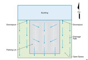
The parking lot scenario consists of a parking lot on a commercial property currently draining to an existing stream directly south of the site. Bank erosion of the existing stream has become evident as well as high pollutant and sediment loads from the site’s runoff. The goal of the project is to implement BMPs onsite to help control the volume of runoff and pollutant load contribution to the stream for the Water Quality Event, without disturbing the existing commercial function of the site. The site conditions for the parking lot scenario are summarized in the Parking Lot Scenario Existing Site Conditions table below, and the existing site layout can be seen in Figure 3.1.1, below.
Parking Lot Scenario Existing Site Conditions
Step 2: Review Pollutant Removal Processes & Identify Potential Practices
Because the goals of the project are to both decrease runoff volume and pollutant loading, the BMPs selected for this site should offer both pollutant removal and volume reduction processes. The Parking Lot Scenario BMP Practice Selection table below summarizes the BMP practice categories and their applicability to this site.
Parking Lot Scenario BMP Practice Selection
Infiltrators, filters, and swales & strips are determined to be the practices to best address the goals of the project for the Parking Lot Scenario. The process of selecting and placing BMPs on a site is typically iterative, working between the site constraints, project goals, and available budget. The approach and considerations for this scenario are discussed in the following sections.
Step 3: Determine Site Constraints & BMP Placement
Existing site conditions cause several constraints regarding placement of BMPs. The most significant of these constraints are available space, existing topography, and regulatory requirements:
- Available Space - The majority of the drainage area is impervious, consisting of building and parking lot space that is necessary for the commercial property to function. BMP selection that will minimize loss of these amenities is a key consideration.
- Topography - Currently runoff generally drains from north to south. More specifically, the parking lot drains to the center aisle, and the building drains to the grassed area on either side of the parking lot before continuing south and offsite. This makes ideal locations for BMPs to maximize stormwater capture the middle of the parking lot, and the open space on the south side of the property.
- Regulatory Requirements - All local, state, and federal regulatory requirements must be met. The design criteria and recommendations from the Minnesota Stormwater Manual will be followed.
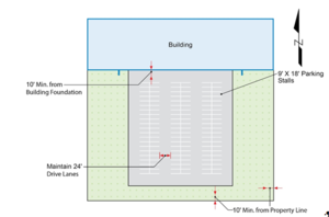
The viable locations for BMP placement identified are the center parking aisles, and the open space on the perimeter of the parking lot. The optimal placement for maximum site runoff capture is in the open space along the southern property edge. Building foundations and property lines are both considered structures of concern when adjacent to infiltration BMPs. It is important to maintain the recommended 10’ minimum setback from each when placing the BMPs. The Parking Lot Scenario BMP Placement & Site Constraints schematic below displays the recommended placement of the BMPs for this site, and site considerations.
Step 4: Select Individual BMPs & Evaluate Range of Performance
As discussed in Step 2, the practices that are most applicable to this site are infiltrators, swales & strips, and filters. In general, filters remove pollutants by physical, chemical, or biological processes that occur while the stormwater moves through the filter media. Depending on the type of filter used, some volume reduction may be recognized through infiltration below an underdrain, or transpiration through vegetation. Filter’s typically have volume and pollutant removal efficiencies of 100% for portions of water that are infiltrated, and have a reduced percentage reduction for stormwater that is filtered and released from the system. Infiltration BMPs however, assume 100% volume reduction and pollutant removal efficiency for all stormwater treated by the BMP. Because the site has both volume reduction and pollutant removal goals, it is recommended to use infiltration BMPs to more effectively reduce the volume of stormwater runoff and pollutant loads. Given the sites well-draining soils, infiltrators are a viable option for this scenario.
Infiltrator: Permeable Pavement
- Replacing a portion of the parking lot with permeable pavement allows for a reduction in impervious area as well as a potential for reduction of stormwater runoff and pollutants through infiltration. For permeable pavement designs with underdrains, the volume of water intercepted by the underdrain can expect a pollutant removal performance of 45% of total phosphorous (TP) and 74 % TSS. If the permeable pavement is designed without an underdrain, the entire volume of runoff entering the system will ultimately be infiltrated, providing nearly 100% TP and TSS removal for treated stormwater.
Infiltrator: Infiltration Basin
- Placement of the secondary treatment train BMP determined to be on the south side of the property backing up directly to the creek is not a highly visible location. For this reason, a highly aesthetic infiltration BMP is not necessary. While bioinfiltration and tree trenches could offer additional performance benefits through biological and microbiological processes, they are not necessary to meet the project goals and could include higher construction and maintenance costs. Additionally, because erosion of the streambed is a concern, utilizing a BMP that offers channel protection through peak discharge attenuation is ideal. An infiltration basin can provide this type of benefit as well as volume reduction and pollutant removal.
Swales & Strips: Grass Channel
- Infiltration basins require use of pretreatment of stormwater before being directed to the practice. Using a swale would both serve as pretreatment, and offer some pollutant removal benefits. Because the infiltration basin will treat the majority of the stormwater, the main purpose of the swale will be to serve as pretreatment and to convey stormwater to the basin. For this reason, a simple grass channel is sufficient. A swale with a bioretention base or check damns could offer additional stormwater volume and pollutant removal benefits, if needed, however, are not necessary with the use of the downstream infiltration basin.
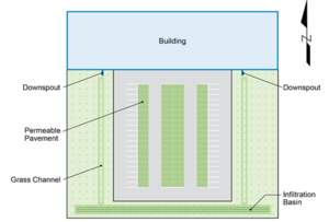
While multiple infiltrator, filter, or swale & strip BMPs could potentially work for this site, it is determined that permeable pavement, grass channels, and an infiltration basin will best meet the goals of the project, while working within site constraints and meeting client budget expectations. Figure 3.1.3 displays the proposed BMP treatment train layout for the parking lot scenario.
Step 5: Size BMPs & Assess Performance
BMP sizing can also be an iterative process between meeting project goals, working within site constraints, meeting regulatory requirements, and meeting client expectations. The MIDS calculator was used to evaluate the performance goals for the site given the drainage area, soil conditions, impervious area, average annual rainfall for the area, and the Water Quality Event retention goal (1.1”). Assumptions included an annual Phosphorus EMC of 0.3 mg/L, and an annual TSS EMC of 54.5 (mg/L). The Parking Lot Scenario Performance Goal table below summarizes the existing site runoff, volume and pollutant retention goals.
Parking Lot Scenario Performance Goal
The BMPs were sized to best meet the project performance goals within the available space on site.
Permeable Pavement
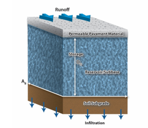
The main sizing considerations for permeable pavement infiltration BMP are the surface area of the permeable pavement, the depth the aggregate reservoir, the porosity of the aggregate media, and the infiltration rate of the underlying soils. Figure 3.1.4 shows the typical configuration of a permeable pavement section.
The amount of impervious area draining from the parking lot is about 0.95 acres. The amount of at-grade contributing impervious drainage area into permeable pavement should not exceed a 5:1 ratio to help reduce the rate of sedimentation. In order to stay within this parameter, an additional permeable pavement parking lane was added on either side of the center aisle, keeping about a 3.2:1 impervious drainage area to permeable pavement area ratio. The permeable pavement BMP is designed to store the entire treatment volume for the Water Quality Event while meeting the MPCA design criteria, requirements and recommendations. The Permeable Pavement Sizing Input Parameters table below displays the remaining sizing input parameters used for the permeable pavement design.
Permeable Pavement Sizing Input Parameters
The infiltration rate of the underlying soils is 0.45 in/hr, and the porosity of the aggregate was assumed to be 0.35 ft3/ft3. These parameters were entered into the MIDS calculator to evaluate performance of the permeable pavement BMP for a runoff volume and pollutant load reductions. These results are summarizes in Table 3.1.5.
Parking lot Permeable Pavement Performance Summary
Grass Channel
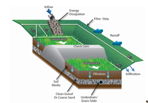
A grass channel, or swale, can have a multitude of different configurations and components depending on its desired functions and site topography. Figure 3.1.5 shows the typical configuration of a swale or strip with various features it may include. As discussed in Section 3.1 Step 4, the primary purpose for the swale at this site is to serve as conveyance and pretreatment for the downstream infiltration basin BMP. For this reason, the main design parameters will include main channel length, width, depth, and slope as well as the swale side slope length. No check dams, soil media, or gravel and underdrain layers are included in this design.
The swale will be placed at the outlet point of the building downspouts to maximize capture of runoff from impervious area. The slope of the main channel is set at 2% to match existing grades of the site. The channel length extends from the downspout outlet to the grassed area south of the parking lot. The grass channels were design to meet the MPCA design criteria, requirements and recommendations. The Grass Channel Sizing Input Parameters table below displays the sizing input parameters used for the grass channel design
Grass Channel Sizing Input Parameters
| Side Slope (V:H) | Channel Length (ft.) | Bottom Width (ft.) | Slope (%) |
|---|---|---|---|
| 1.4 | 216 | 4 | 2 |
These parameters were entered into the MIDS calculator to evaluate performance of each of the grass channel BMPs for a runoff volume and pollutant load reductions, as well as to gain an understanding of the outflow that will be directed to the infiltration basin BMP downstream in the treatment train. The MIDS Calculator evaluates swale side slopes as an upstream BMP to swale main channel. However, virtually no volume or pollutant removal benefits were recognized for the swale side slope. The sum of results for the grass channel BMPs are summarized in Table 3.1.7.
Grass Channels Performance Summary
Infiltration Basin
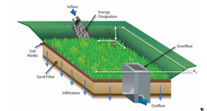
The primary goal when sizing the infiltration basin is to treat the remaining stormwater runoff from the site not previously removed by upstream treatment train BMPs. Figure 3.1.6 shows a typical configuration and components of an infiltration basin. The inflow will be directed from the grass channels on the east and west side of the parking lot directly upstream of the basin. The basin itself will rely solely on infiltration into existing soils in the ponding area of the BMP within the required 48 hour drawdown time. Flows in excess will be directed to the overflow and released at non-erosive rates. No additional sand layer is included for this site.
The major constraints for sizing the basin include the ponding area, the basin area, and the depth of the ponding area. The available space in the open area south of the parking limits the maximum ponding area of the basin. This is controlled by a required 10’ setback from the property line, as well as a desired offset form the parking lot to avoid the infiltration basin being directly connected to structure or pavement foundations to avoid seepage and frost heave concerns, per MPCA design criteria. This additionally provides pretreatment of any direct runoff not routed through the upstream BMPs, allowing for impervious surface disconnection over a grass strip between the parking lot and the infiltration basin. The basin itself will extend the entire width of the parcel, less the required 10’ offset in order to maximize stormwater capture from the site. The sizing parameters for the infiltration basin are described in the Infiltration Basin Sizing Input Parameters table below.
Infiltration Basin Sizing Input Parameters
These parameters were entered into the MIDS Calculator to evaluate the performance of the BMP. The results are summarized in the Infiltration Basin Performance Summary table below.
Infiltration Basin Performance Summary
Overall Parking Lot BMP Treatment Train Performance
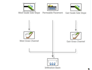
The treatment train as a whole was evaluated using the MIDS Calculator. The swale side slopes were assumed to drain to the swale main channel and then to the infiltration trench, while the permeable pavement acts as stand-alone BMP able to treat the entire volume of stormwater collected for the 1.1” event. This configuration is shown in the Parking Lot BMP Treatment Train MIDS Calculator Schematic.
The treatment train provides an annual removal efficiency of 96% runoff volume for the site as well as 97% Total Phosphorous and 98% Total Suspended Solids. The MIDS Calculator annual performance results of the BMP treatment train as a whole are summarized in Table 3.1.10.
Parking Lot Annual BMP Treatment Train Performance Summary
Step 6: Review Construction & Operations Criteria
Each of the BMPs included in the treatment train have unique criteria for construction and operations. Information regarding construction and operations should be reviewed in detail before design and construction of the BMPs take place. Available information for each of the BMPs used in the Parking Lot Scenario are provided in Table 3.1.11.
