Summary of changes in Version 4 Minimal Impact Design Standards (MIDS) Calculator
Version 3 of the Minimal Impact Design Standards (MIDS) Calculator (Calculator) was updated to Version 4 in Fall, 2020. This page provides a summary of updates from Version 3 to Version 4 of the Calculator.
Contents
- 1 Downloading Version 4
- 2 Constructed ponds with an iron bench
- 3 Green roofs - intensive roofs
- 4 Updated pollutant removal values
- 5 Bioretention media mix options
- 6 Media amendments
- 7 Tree rooting depth
- 8 Tree interception
- 9 Viewing phosphorus results on Results tab
- 10 Infiltration restriction for D soils
- 11 Accounting for bypass
- 12 Sand filter design levels and credits for dissolved phosphorus
- 13 Swale configuration in the MIDS Calculator
- 14 Changes that were not made to Version 4
Downloading Version 4
Version 4 of the Calculator can be downloaded here.
Version 3 files are not compatible with Version 4. You can download Version 4 to your computer without having to replace Version 3. Thus, you may have both Versions 3 and 4 on your machine, allowing you to continue working with Version 3 files while also working with Version 4 files.
Constructed ponds with an iron bench
| Pollutant removal percent for different pond conditions and design levels | ||||||
| Design level | Particulate phosphorus | Dissolved phosphorus | TSS | |||
| No amendment | With amendment | No amendment | With amendment | No amendment | With amendment | |
| 1 | 60 | 60 | 0 | 40 | 60 | 60 |
| 2 | 84 | 84 | 8 | 40 | 84 | 84 |
| 3 | 90 | 90 | 23 | 40 | 90 | 90 |
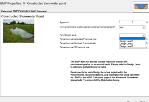
Users can now specify a constructed stormwater pond with an iron-enhanced filtration bench to allow dissolved phosphorus removal. To achieve this, the Calculator incorporates the same question and same dissolved phosphorus removal percent as for sand filter3 in Version 3:
"Have amendments to attenuate phosphorus been incorporated?"
Although the question does not specify iron as the amendment, iron is the most likely amendment, based on current knowledge and practice. Answering "YES" to the question about an amendment results in dissolved phosphorus reduction of 40 percent. Removal of particulate phosphorus and total suspended solids are unchanged. Design level requirements are the same with or without an amendment. It is assumed that the amendment is incorporated following recommended design, construction, and maintenance guidance in this manual.
For information on using the constructed pond BMP in the Calculator, go to this link.
This change was made in the Calculator because there are numerous ponds constructed with iron benches. Performance results have been mixed, but data suggests that properly designed, constructed, and maintained iron benches retain dissolved phosphorus.
Green roofs - intensive roofs
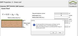
Users can now incorporate intensive green roofs into a green roof design. This change was created by allowing the user to select a media depth greater than 4 inches. When the user specifies a depth greater than 4 inches the following warning appears:
"you have specified an intensive green roof design. See the green roof design section in the Stormwater Manual."
Note that there is some variability in the definition of an intensive green roof in the literature (e.g. 4, 6 or 8 inches being values cited in different references).
Other inputs and restrictions on green roof design are unchanged. For information on using green roof BMPs in the Calculator, go to this link.
To view the green roof section in this manual, link here.
This change was incorporated because there are intensive green roofs and increased media depth has a significant effect on the volume of water that can be retained.
Updated pollutant removal values
Pollutant removal vales were updated for some BMPs. These changes were based on published research and to improve consistency between the Calculator and values posted in this Manual. An important source of information used in evaluating these data was the International BMP Database (IBMPD).
- Reduce the wet swale removal rate for TSS from 68% to 35%. Published research, including the IBMPD, show removal rates between 20 and 40 percent. Higher values are reported in the literature, but often these values are associated with swale systems that include pretreatment or other specific design features.
- Adjust the particulate phosphorus (PP) removal numbers down to match TSS removal for Permeable Pavement (74%), Swale Main Channel w/o underdrain (68%) and Level 1 Stormwater Pond (60%). Version 3 included PP removal values greater than TSS removal, which is not physically possible unless the BMP was selectively removing sediment with a greater PP concentration. Removal values in Version 3 were 82, 73, and 62 percent for permeable pavement, swale, and Level 1 pond, respectively.
- For bioretention basin with underdrain, tree trench with underdrain, and swale with underdrain, when a user includes an amendment for phosphorus retention, change the particulate phosphorus retention from 0% to 40%. This was an error in Version 3 and has been changed to align particulate and dissolved phosphorus removal in BMPs amended to remove phosphorus.
- As discussed above, pond benches with iron amendments receive a 40 percent credit for dissolved phosphorus].
- Iron-enhanced sand filters meeting Tier 2 requirements now get a 60 percent dissolved phosphorus reduction.
Bioretention media mix options
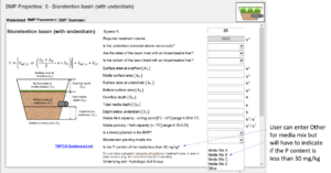
For bioretention basin with underdrain and tree trench with underdrain, for the question Bioretention planting media mix, add Other. In addition to Mixes A and B, if the user selects Other for media mix, display the cell for the question Is the P content of the media less than 30 mg/kg? (i.e. this cell is greyed out when the user selects Mix C or Mix D).
This change was made because a variety of media mixes are being used in stormwater applications, including site-specific mixes. Phosphorus removal and phosphorus leaching from media is a function of the phosphorus concentration and form of phosphorus in the media. Research suggests that media with a phosphorus concentration greater than about 30 mg/kg will leach phosphorus. This is an area of active research. For more information on engineered media and phosphorus, link here. For more information on compost, which is typically the source of phosphorus leached from engineered media, link here.
Media amendments
For bioretention and tree trench with underdrain, the question Is a soil amendment used to attenuate phosphorus? was changed to Do you have a properly designed phosphorus treatment layer or area in your system (e.g. iron enhanced layer)? and a link is provided to a section discussing layered systems. The change was made to more accurately reflect the systems being built, which to date are exclusively layered systems. For information on layered systems, link here.
Tree rooting depth
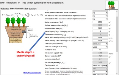
In Version 3 of the Calculator, for tree trenches, the User input media depth and this was used to compute the volume of soil accessible by the tree. Because it does not accurately reflect tree rooting depth, this restricted the number of trees that could be incorporated into a BMP. Because tree roots can extend below the media into the underlying soil, this input in the Calculator was changed from media depth to media depth plus underlying soil. This allows the User to correctly simulate the active rooting zone and allows more trees to be incorporated into the design. This in turn affects the volume of water that is intercepted and evapotranspired by trees, thus increasing water retention at a site.
Tree interception
The value for tree interception was updated. When tree interception was initially incorporated into the Minnesota Stormwater Manual and the MIDS Calculator, research was limited. Research conducted over the past 5-10 years indicates the initial values for tree interception were low. MPCA executed a work order to conduct a literature review to determine if the tree interception value in the Calculator should be modified. The Contractor submitted a technical memo to the MPCA, which included the following recommendations.
- Setting the annual rainfall interception performance of deciduous and coniferous trees at 30% and 57%, respectively. These values are based on the average of the performances documented in all reviewed studies for trees and climates that are applicable to Minnesota.
- Setting the rainfall interception depth capacity of deciduous and coniferous trees at 0.14 inches and 0.40 inches, respectively. This interception depth translates into an annual rainfall interception performance of 30% and 57% respectively, thereby aligning both tree metrics.
These changes were incorporated into Version 4 of the Calculator. Combined with the modification for the input on tree media depth and underlying soil (described above), water retention by interception increased significantly, though it still makes up a relatively small amount of retention at a site.
The technical memo referenced above can be found here.
Viewing phosphorus results on Results tab
The following additions were made to the Results tab in the Calculator.
- On the Results screen, under Summary Information, create a line in the P section for Total P removed by BMPs (add particulate and dissolved removed). Units for this are lbs.
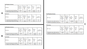
- On the Results screen, in the BMP Summary section, add a section called Total Phosphorus Summary, which contains information similar to the other P sections.
Infiltration restriction for D soils
For infiltration BMPs (BMPs without an underdrain), if the user answered yes to the question Are you using the calculator to determine compliance with a Construction Stormwater permit? on the Site Information tab, do not allow the user to select D soils. If the user selects a user-defined infiltration rate, ensure this value is >= 0.2 inches per hour.
The Construction Stormwater Permit prohibits infiltration on D soils. For more information, link here.
Accounting for bypass
In Version 3 of the Calculator, runoff that bypassed a BMP with an underdrain or was treated by a non-volume reduction BMP and that was routed to a downstream BMP, was considered to be treated. The result was that the Calculator overestimated pollutant removal for these situations. Because it is challenging to build code into the Excel spreadsheet to account for this, the User is asked to input the percent bypass for a BMP. The User must therefore determine bypass. The following changes were implemented.
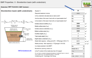
- For non-volume reduction BMPs and BMPs with an underdrain, request the user to manually input a “bypass percentage” (e.g., 28% bypass) within the BMP properties dialog box.
- For non-volume reduction BMPs and BMPs with an underdrain, track treated vs untreated pollutant load and assign a fractional adjustment of the percent reduction (PR%) applied to the treated load.
The figure on the right illustrates the situation. In condition A, a biofiltration practice (bioretention with underdrain) is sized to meet the MIDS performance goal of 1.1 inches (3993 ft3 of runoff from 1 acre of impervious surface). Some TSS and TP are filtered by the media, and this filtered water is captured by the underdrain and returned to the stormwater conveyance, where it is routed to the downstream infiltration practice. TP and TSS routed to the downstream BMP are 0.60 and 46.3 pounds, respectively. In condition B, the biofiltration basin is sized to treat 25 percent less runoff, with the result that less water is treated and less pollutant removed. TP and TSS routed to the downstream BMP are 0.66 and 50.8 pounds, respectively. No bypass was included for either the adequately sized bmp or the undersized bmp. There is always some bypass for a bmp, even when sized to meet the performance goal. The amount of bypass increases as a practice is undersized. Bypass therefore applies to all sizing conditions, not just undersized practices.
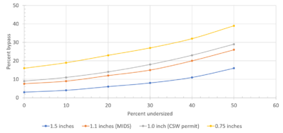
The percent bypass can be determined using the adjacent curves. Identify your performance goal and the sizing of your practice, determine the percent bypass from the curve, and enter that value into the calculator. More detailed information can be found on this page.
The BMPs to which this option applies include bioretention with underdrain, tree trench with underdrain, dry swale with underdrain, constructed pond, constructed wetland, sand filter, and wet swale.
Sand filter design levels and credits for dissolved phosphorus
Three design levels were created for sand filters. These are described below. NOTE: PP=particulate phosphorus, DP=dissolved phosphorus, TP=total phosphorus
- Level 1: TSS removal = 75%, PP removal = 41%
- Provides less than full water quality volume treatment, or
- Pretreatment less than 25% of water quality volume, or
- Filter bed is less than 5% of contributing drainage area
- Level 2: TSS removal = 85%, PP removal = 47%
- Provides full water quality volume treatment, and
- Pretreatment 25% or more of water quality volume, and
- Filter bed > 5% of contributing drainage area
- Level 3: TSS removal = 90%, PP removal = 50%
- Exceeds water quality volume by more than 50%, and
- Pretreatment 25% or more of water quality volume, and
- Filter bed > 10% of contributing drainage area
For each of these design levels, the PP credit was calculated as 55 percent of the TSS credit, based on an assumption that PP is 55 percent of TP and there is no preferential retention of P based on particle size.
The user must also indicate if an amendment to attenuate phosphorus is incorporated into the bmp. The user can select from a dropdown with the following options.
- No amendment
- Amendment added, Tier 1
- Amendment added, Tier 2
The conditions for Tier 1 and Tier 2 are as follows.
- No amendment added to attenuate P; DP removal = 0%
- Tier 1: Amendment added and meets the following; DP removal = 40%
- Iron enhanced system, and
- Iron 5-8% by weight, high purity iron (90%+ elemental iron) with little or no toxic impurities (e.g., copper, cadmium, lead, etc.), and reactive with phosphate, and
- Inspect IESFs at least once annually, with more frequent inspections (monthly or quarterly) during the first 1-2 years if needed to ensure construction was successful, and
- Annually or as needed remove vegetation and accumulated sediment (as needed, typically once 5-10 years depending on contributing sediment and pretreatment), and
- Rake surface with a steel-tipped rake to break up oxidized iron clumps or crust that may form, and
- System designed to allow drying (e.g. exposed to sunlight, drawdown requirement)
- Tier 2: Amendment added and meets the following; DP removal =60%
- Iron enhanced system, and
- Iron 5-8% by weight, high purity iron (90%+ elemental iron) with little or no toxic impurities (e.g., copper, cadmium, lead, etc.), and reactive with phosphate, and
- Inspect IESFs at least once annually, with more frequent inspections (monthly or quarterly) during the first 1-2 years if needed to ensure construction was successful, and
- Annually or as needed remove vegetation and accumulated sediment (as needed, typically once 5-10 years depending on contributing sediment and pretreatment), and
- Rake surface with a steel-tipped rake to break up oxidized iron clumps or crust that may form, and
- System designed to allow drying (e.g. exposed to sunlight), and
- Level spreader, modified pond inlets, or other method or design for spreading water across the system, and
- Enhanced pretreatment designed to remove organic material (see Pretreatment Practice Selection Tool to identify practices effective at removing debris and solids), and
- Designed to be offline such that flows beyond the water quality volume flows are diverted around the system, and
- Inspection and maintenance agreement established that identifies the entity responsible for inspection and maintenance.
The default is no amendment.
Swale configuration in the MIDS Calculator
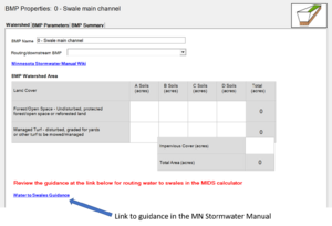
Because of the way swales are configured in the MIDS Calculator, there is a potential for inaccurate accounting of drainage areas. The MIDS Calculator separates swale side slopes and swale main channels into separate best management practices. Consequently, we have observed that Calculator Users will sometimes route watershed acres to both the side slope and the main channel even though these are part of a single swale system. Watershed acres should be routed to either the side slope or the main channel, but not to both.
The reason side slope and main channel are separate in the Calculator, even though they may be part of the same swale system, is because infiltration and pollutant retention calculations differ for the side slope and the main channel. Thus there is a different set of equations for side slope and main channel.
Programming the Calculator so that a single swale system would account for volume and pollutant retention on the side slope and main channel proved challenging, so the alternative was to develop guidance for Users. This guidance on how to design a swale system is found here.
Changes that were not made to Version 4
The original work order for Version 4 included some tasks that were not completed due to difficulty in programming them into the MIDS Calculator. Those include the following.
- Version 3 files cannot be migrated to Version 4. Instead, the User can have both Version 3 and Version 4 on their computer, thus allowing them to continue to use Version 3 files.
- BMPs cannot be copied. While it would be convenient to copy redundant BMPs instead of building them in the Calculator, the effort needed to accomplish this was deemed too great.
- As discussed above, we explored the potential for combining side slope and main channel swales into a single BMP to avoid confusion in routing these BMPs, but it was deemed sufficient to provide guidance to Users, provided this guidance was clearly communicated to Users (e.g. note and link in the Calculator, webinars, training, guidance in the Manual).
- A separate water quality calculator was to be built using the MIDS platform. The water quality calculator was intended to include the following.
- Allow the user to select land use from a dropdown list. Land use would be linked to an event mean concentration for TP and TSS for that land use.
- Allow the user to modify the fraction of TP that is in dissolved and particulate form.
- Allow the user to input a rainfall value rather than link rainfall to zip code. This would prompt a warning in the Calculator: Note that calculations in the MIDS Calculator are based on long-term simulation for Minnesota and may not be applicable to other locations
- To provide Users with more flexibility in using the MIDS Calculator for water quality simulations, such as for TMDL compliance, we created a guidance page.
This page was last edited on 1 July 2024, at 20:35.

