Difference between revisions of "Water quality benefits of Green Stormwater Infrastructure"
m (→References) |
|||
| Line 146: | Line 146: | ||
==References== | ==References== | ||
| − | *[https://cfpub.epa.gov/si/si_public_record_report.cfm?dirEntryId=291092 ] | + | *Berndtsson, J.C., L. Bengtsson, and K. Jinno. 2009. [https://www.sciencedirect.com/science/article/pii/S0925857408002024 Runoff water quality from intensive and extensive vegetated roofs]. Ecological Engineering |
| − | + | Volume 35, Issue 3, Pages 369-380. | |
| − | *[https://www.epa.gov/sites/production/files/2015-11/documents/stormwater2streettrees.pdf] | + | *Davis, A.P. 2007. ''Performance of Bioretention: Water Quality''. Environmental Engineering ScienceVol. 24, No. 8. https://doi.org/10.1089/ees.2006.0190. |
| − | + | *OConnor, T., P. Culligan, T. Carson, S. Gaffin, R. Gibson, R. Hakimdavar, D. Hsueh, N. Hunter, D. Marasco, AND W. McGillis. 2014. [https://cfpub.epa.gov/si/si_public_record_report.cfm?dirEntryId=291092 Evaluation of Green Roof Water Quantity and Quality Performance in an Urban Climate]. U.S. EPA Office of Research and Development, Washington, DC, EPA/600/R-14/180. | |
| + | *United States EPA. 2013. [https://www.epa.gov/sites/production/files/2015-11/documents/stormwater2streettrees.pdf Stormwater to Street Trees: Engineering Urban Forests for Stormwater Management]. EPA 841-B-13-001. | ||
*[https://www.usgs.gov/science/evaluating-potential-benefits-permeable-pavement-quantity-and-quality-stormwater-runoff?qt-science_center_objects=0#qt-science_center_objects] | *[https://www.usgs.gov/science/evaluating-potential-benefits-permeable-pavement-quantity-and-quality-stormwater-runoff?qt-science_center_objects=0#qt-science_center_objects] | ||
*[https://www.epa.gov/soakuptherain/soak-rain-permeable-pavement] | *[https://www.epa.gov/soakuptherain/soak-rain-permeable-pavement] | ||
Revision as of 16:31, 16 November 2022
This page provides information on the water quality benefits of green stormwater infrastructure (GSI) practices ( best management practices). The water quality benefit of a practice is defined by its ability to attenuate pollutants from stormwater runoff and prevent them from reaching receiving waters. All GSI practices provide water quality benefits since that is their primary function.
These benefits vary between each practice, primarily as a result of the mechanism by which pollutants are attenuated.
- Constructed ponds ( wet ponds) and wetlands ( stormwater wetlands) remove pollutants through sedimentation. This removes medium- to large- diameter particles and pollutants attached to those particles, though effectiveness varies with design of the practice. See Calculating credits for stormwater ponds. For more information on sedimentation processes, link here.
- Filtration practices include bmps that have an underdrain ( biofiltration, permeable pavement, tree trench, swales, green roofs, and media filters) or bmps that trap sediments from flowing water (vegetated filter strips, swales, green roofs).
- Infiltration practices remove pollutants by capturing runoff and infiltrating it vertically into underlying soil, the vadose zone, and groundwater. Attenuation occurs primarily through adsorption and filtering, though dilution in groundwater may also be a mechanism for reducing pollutant concentrations.
| Practice | Water quality benefit | Notes |
|---|---|---|
| Bioretention and infiltration | ||
| Tree trench and tree box | ||
| Green roof | ||
| Vegetated swale | ||
| Vegetated filter strip | ||
| Permeable pavement | ||
| Constructed wetland | ||
| Rainwater harvesting | ||
| Level of benefit: ◯ - none; ◔; - small; ◑ - moderate; ◕ - large; ● - very high | ||
Contents
- 1 Green infrastructure and multiple benefits
- 2 Pollutant removal percentages for bmps
- 3 Infiltration practices
- 4 Bioretention
- 5 Tree Trench
- 6 Permeable Pavement
- 7 Green Roofs
- 8 Water Re-use and Harvesting
- 9 Constructed Ponds and Wetlands
- 10 Swale with Check Dam (with and without underdrain)
- 11 References
Green infrastructure and multiple benefits
Green infrastructure (GI) encompasses a wide array of practices, including stormwater management. Green stormwater infrastructure (GSI) encompasses a variety of practices primarily designed for managing stormwater runoff but that provide additional benefits such as habitat or aesthetic value.
There is no universal definition of GI or GSI (link here fore more information). Consequently, the terms are often interchanged, leading to confusion and misinterpretation. GSI practices are designed to function as stormwater practices first (e.g. flood control, treatment of runoff, volume control), but they can provide additional benefits. Though designed for stormwater function, GSI practices, where appropriate, should be designed to deliver multiple benefits (often termed "multiple stacked benefits". For more information on green infrastructure, ecosystem services, and sustainability, link to Multiple benefits of green infrastructure and role of green infrastructure in sustainability and ecosystem services.
Pollutant removal percentages for bmps
The adjacent table provides a summary of estimated pollutant removal for stormwater bmps. However, pollutant removal is a function of many factors, including design, construction, and maintenance of the BMP; quality of incoming stormwater; time of year; rainfall and watershed characteristics; and so on. The user is encouraged to read the section called Factors affecting pollutant removal.
Median pollutant removal percentages for several stormwater BMPs. Sources. More detailed information and ranges of values can be found in other locations in this manual, as indicated in the table. NSD - not sufficient data. NOTE: Some filtration bmps, such as biofiltration, provide some infiltration. The values for filtration practices in this table are for filtered water.
Link to this table
| Practice | TSS | TP | PP | DP | TN | Metals1 | Bacteria | Hydrocarbons |
|---|---|---|---|---|---|---|---|---|
| Infiltration2 | 3 | 3 | 3 | 3 | 3 | 3 | 3 | 3 |
| Biofiltration and Tree trench/tree box with underdrain | 80 | link to table | link to table | link to table | 50 | 35 | 95 | 80 |
| Sand filter | 85 | 50 | 85 | 0 | 35 | 80 | 50 | 80 |
| Iron enhanced sand filter | 85 | 65 or 746 | 85 | 40 or 606 | 35 | 80 | 50 | 80 |
| Dry swale (no check dams) | 68 | link to table | link to table | link to table | 35 | 80 | 0 | 80 |
| Wet swale (no check dams) | 35 | 0 | 0 | 0 | 15 | 35 | 35 | NSD |
| Constructed wet ponds4, 5 | 84 | 50 or 685 | 84 | 8 or 485 | 30 | 60 | 70 | 80 |
| Constructed wetlands | 73 | 38 | 69 | 0 | 30 | 60 | 70 | 80 |
| Permeable pavement (with underdrain) | 74 | 41 | 74 | 0 | NSD | NSD | NSD | NSD |
| Green roofs | 85 | 0 | 0 | 0 | NSD | NSD | NSD | NSD |
| Vegetated (grass) filter | 68 | 0 | 0 | 0 | NSD | NSD | NSD | NSD |
| Harvest and reuse | Removal is 100% for captured water that is infiltrated. For water captured and routed to another practice, use the removal values for that practice. | |||||||
TSS=Total suspended solids, TP=Total phosphorus, PP=Particulate phosphorus, DP=Dissolved phosphorus, TN=Total nitrogen
1Data for metals is based on the average of data for zinc and copper
2BMPs designed to infiltrate stormwater runoff, such as infiltration basin/trench, bioinfiltration, permeable pavement with no underdrain, tree trenches with no underdrain, and BMPs with raised underdrains.
3Pollutant removal is 100 percent for the volume infiltrated, 0 for water bypassing the BMP. For filtered water, see values for other BMPs in the table.
4Dry ponds do not receive credit for volume or pollutant removal
5Removal is for Design Level 2. If an iron-enhanced pond bench is included, an additional 40 percent credit is given for dissolved phosphorus. Use the lower values if no iron bench exists and the higher value if an iron bench exists.
6Lower values are for Tier 1 design. Higher values are for Tier 2 design.
Infiltration practices
Bioretention
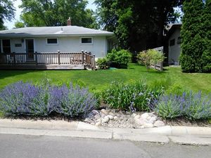
Bioretention is an excellent stormwater treatment practice due to the variety of pollutant removal mechanisms, including vegetative filtering, settling, evaporation, infiltration, transpiration, biological and microbiological uptake, and soil adsorption. Bioretention can be designed as an effective infiltration / recharge practice, particularly when parent soils have high permeability (> ~ 0.5 inches per hour). Bioretention designed for infiltration ( bioinfiltration) removes 100 percent of pollutants for the portion of runoff water that is infiltrated, although there may be impacts to shallow groundwater. Bioretention designed as filtration ( biofiltration) employs engineered media that is effective at removing solids, most metals, and most organic chemicals. Removal of phosphorus depends on the media (link here). Links to water quality information for bioretention - [1]; [2]
The following design considerations can improve the water quality function of bioretention practices.
- Maximize infiltration by designing with the maximum ponded depth that can be infiltrated in 48 hours, up to 1.5 feet (to protect vegetation). Where space allows, surface area can also be increased. Utilize multiple bioretention practices in series. On lower permeability soils where an underdrain is used, raise the underdrain to the maximum extent possible, allowing water stored in the bioretention media below the underdrain to drain in 48 hours. Use an upturned elbow in underdrained systems.
- For bioinfiltration (bioretention without an underdrain), use a high organic matter media to maximize pollutant removal
- For biofiltration (bioretention with an underdrain), use a media mix that does not export phosphorus or use an amendment to attenuate phosphorus.
See Calculating credits for bioretention
Tree Trench
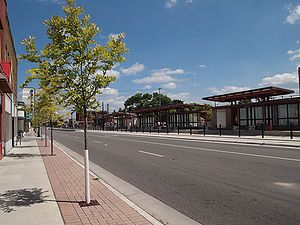
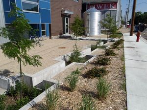
Tree trenches and tree boxes are an excellent stormwater treatment practice due to the variety of pollutant removal mechanisms including vegetative filtering, settling, evaporation, infiltration, transpiration, biological and microbiological uptake, and soil adsorption. Tree trenches and tree boxes can be designed as an effective infiltration / recharge practice, particularly when parent soils have high permeability (> ~ 0.5 inches per hour). Link to water quality information for tree trench/tree box - [3]
The following design considerations can improve the water quality benefits of tree trenches.
- Maximize infiltration by designing with the maximum ponded depth that can be infiltrated in 48 hours, up to 1.5 feet (to protect vegetation). Where space allows, surface area can also be increased.
- Utilize multiple bioretention practices in series.
- On lower permeability soils where an underdrain is used, raise the underdrain to the maximum extent possible, allowing water stored in the engineered media below the underdrain to drain in 48 hours. Use an upturned elbow in underdrained systems.
- For bioinfiltration (bioretention without an underdrain), use a high organic matter media to maximize pollutant removal.
- For biofiltration (bioretention with an underdrain), use a media mix that does not export phosphorus or use an amendment to attenuate phosphorus.
See Calculating credits for tree trenches and tree boxes
Permeable Pavement
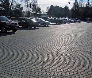
Permeable pavement are an excellent stormwater practice that allows for the absorption and infiltration of rainwater and snow melt onsite. It can reduce the concentration of some pollutants either physically (by trapping it in the pavement or soil), chemically (bacteria and other microbes can break down and utilize some pollutants), or biologically (plants that grow in-between some types of pavers can trap and store pollutants)(5). Permeable pavement functioning as an infiltration practice (no underdrain) effectively treats most pollutants, including dissolved pollutants. When an underdrain is employed, permeable pavement is effective at removing solids and pollutants attached to those solids. Additionally, permeable pavements can reduce the need for road salt (6).
The following design considerations may improve the water quality benefits of permeable pavement.
- Ensure the subgrade is flat. Since roads are typically sloped, utilize terracing in the subgrade to achieve flat slopes. See page 5 of the North Carolina design guidance.
- Incorporate signage into the design to ensure maintenance activities do not affect the infiltration properties of the pavement.
- Design to maximize retention time and prevent short-circuiting. Storage may be increased by use of geotextile subgrades. An example is presented by Nnadi et al, (2014).
- Plan for the expected loading on the permeable pavement and ensure capabilities and reduce compaction or clogging
- Use in conjunction with other treatments to establish a treatment train or reuse water on site
- Some research has been conducted into use of geotextiles and other amendments for enhancing water quality treatment. See Ostrom and Davis (2019) and Nnadi et al. (2014).
See Calculating credits for permeable pavement
Green Roofs
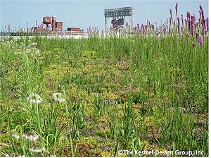
Green roofs provide stormwater treatment benefits, but because pollutant concentrations are generally low, these benefits are limited. Pollutant removal mechanisms include filtering, evaporation, transpiration, biological and microbiological uptake, and soil adsorption.
Green roofs employ engineered media that is effective at removing solids, most metals, and most organic chemicals. Green roofs are generally not effective at retaining phosphorus because of the organic matter content in the media. They therefore are likely to lose phosphorus during the first years after establishment, but loss may gradually diminish over time. Use of low organic matter media, media that does not leach phosphorus (e.g. peat), or amendments (e.g. iron filings) may minimize or eliminate phosphorus losses from green roofs.
See Calculating credits for green roofs and this technical support document.
Water Re-use and Harvesting
Water re-use and water harvesting facilities can help improve water quality by capturing stormwater runoff and reducing offsite discharges into the storm sewer system and nearby water resources. The nature of stormwater re-use facilities varies widely, thus there is great variability in their effectiveness to remove storm water pollutants. Most water re-use projects have been developed to meet non-potable water demands, such as agriculture, landscape, public parks, irrigation, etc. In these cases, the captured stormwater is removed from the waste stream and prevented from reaching receiving waters. Water re-use systems can be used to create or enhance wetlands and riparian (stream) habitats for streams that have been impaired or dried from water diversion, thus enhancing the water quality benefits of these other practices.
The following design considerations may enhance the water quality benefits of harvest and reuse systems.
- The designer should consider the project site pollutant sources during design and determine if additional stormwater treatment measures are required for use, what level of pretreatment is needed, and whether first flush diverters are appropriate. For more information on pollutant sources and pretreatment needs see Water quality considerations for stormwater and rainwater harvest and use/reuse. Also see information on Pretreatment.
- The designer should consider first flush diverters in the collection system design to bypass high pollution loads during snowmelt or pollutant laden events when necessary to meet the requirements of the water use. However, first flush diverters should be utilized with caution ([4]; [5]).
- Designer should place the appropriate settlement and solid removal procedures in the treatment train to prevent their entry into the reuse containment system
- Design the site container to maximize capture and storage of runoff and prevent short-circuiting during rainfall events. See Determining the appropriate storage size for a stormwater and rainwater harvest and use/reuse system and Estimating the water balance for a stormwater and rainwater harvest and use/reuse site.
See Calculating credits for stormwater and rainwater harvest and use/reuse
Constructed Ponds and Wetlands
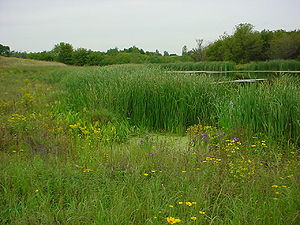
Pollutants are removed from stormwater runoff in a wetland through uptake by wetland vegetation and biota (algae, bacterial), vegetative filtering, soil adsorption, and gravitational settling in the slow moving marsh flow. Volatilization and chemical activity can also occur, breaking down and assimilating a number of other stormwater contaminants such as hydrocarbons. Wetlands effectively remove solids and pollutants associated with solids. They are only moderately effective at removing nitrogen and phosphorus. Some designs or poorly designed and maintained wetlands may export phosphorus. For information on pollutant removal for stormwater wetlands, link to Calculating credits for stormwater wetlands.
CAUTION: Using constructed wetlands for extensive water quality treatment may impair the wetland for other functions, such as habitat.
The following design considerations may improve the water quality benefits of constructed ponds and wetlands (Balderas-Guzman et al., 2018)
- Distribute constructed wetlands systemically throughout a watershed to increase potential for delivering networked benefits
- Design to maximize retention time and prevent short-circuiting
- Create ecological diversity within the wetland to expose water to a variety of conditions where different treatment processes can take place
- Create shallow zones were water will come into contact with plant roots and microbes and deeper zones where anaerobic processes can take place
- Utilize a length to width ratio of 20:1
- Construct multiple wetland cells
- Ensure adequate pretreatment to minimize pollutant loading that might impair other benefits, such as habitat
See Calculating credits for stormwater wetlands
Swale with Check Dam (with and without underdrain)
Water quality benefits of swales depends on the type of swale ([6]). See Terminology for swales.
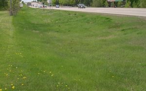
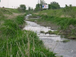
- Dry swales: Water quality benefits of dry swales primarily depend on the presence or absence of check dams and underlying soils. When impermeable check dams are used on permeable soils (hydrologic group A or B soils), swales act as infiltration practices and provide water quality benefits similar to other infiltration practices. If check dams are permeable, swales provide water quality treatment through sedimentation processes. When check dams are absent, swales may provide some filtration of water by vegetation and some infiltration if underlying soils are permeable.
- Wet swales: Wet swales are generally ineffective for water quality treatment.
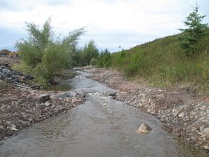
- Step pools: Similar to dry swales, step pools can provide effective water quality treatment when impermeable check dams are employed on permeable soils.
The following design considerations may improve the water quality benefits of swales. (Guzman et al., 2018; [7]; [8]).
- If underlying soils are permeable (HSG A or B), incorporate impermeable check dams into the design to promote infiltration. For wet swales incorporate permeable check dams to slow water movement and enhance filtration of solids.
- For infiltration swales (swales without an underdrain), use a high organic matter media to maximize pollutant removal
- Utilize side slopes as pretreatment by incorporating appropriate vegetation and geometry (e.g. dense grass, increased surface roughness, gentler and longer slopes)
- Select vegetation with dense root systems
- For swales (swales with an underdrain), use a media mix that does not export phosphorus or use an amendment to attenuate phosphorus.
See Calculating credits for dry swale (grass swale), Calculating credits for wet swale (wetland channel), and Calculating credits for high-gradient stormwater step-pool swale.
References
- Berndtsson, J.C., L. Bengtsson, and K. Jinno. 2009. Runoff water quality from intensive and extensive vegetated roofs. Ecological Engineering
Volume 35, Issue 3, Pages 369-380.
- Davis, A.P. 2007. Performance of Bioretention: Water Quality. Environmental Engineering ScienceVol. 24, No. 8. https://doi.org/10.1089/ees.2006.0190.
- OConnor, T., P. Culligan, T. Carson, S. Gaffin, R. Gibson, R. Hakimdavar, D. Hsueh, N. Hunter, D. Marasco, AND W. McGillis. 2014. Evaluation of Green Roof Water Quantity and Quality Performance in an Urban Climate. U.S. EPA Office of Research and Development, Washington, DC, EPA/600/R-14/180.
- United States EPA. 2013. Stormwater to Street Trees: Engineering Urban Forests for Stormwater Management. EPA 841-B-13-001.
- [9]
- [10]
- [11]
- [12]
- [13]

