Green Infrastructure: Filtration practices can be an important tool for detention of stormwater runoff and treatment of pollutants in stormwater runoff. If the practice utilizes vegetation, additional benefits may include cleaner air, carbon sequestration, improved biological habitat, and aesthetic value.
Filtration practices treat stormwater by filtering pollutants. They are effective at attenuating suspended sediment and pollutants associated with that sediment. Most filtration practices utilize an underdrain and engineered soil media to attenuate pollutants and can be sized, in appropriate conditions, to treat the water quality volume. Some infiltration and/or loss of water through evapotranspiration occurs in most filtration practices. Filtration best management practices (BMPs) include, but are not limited, to
- biofiltration (bioretention with an underdrain),
- permeable pavement with an underdrain,
- tree trenches and tree boxes with an underdrain,
- dry swale with an underdrain (with or without check dams),
- wet swales,
- sand filter; and
- green roofs.
Raising an underdrain above the bottom of the filtration practice increases infiltration. However, the practice still functions as a filtration practice. For more information on practices with a raised underdrain, link here.
Contents
- Biofiltration basin (bioretention with an underdrain)
- Permeable pavement (with an underdrain)
- Tree box/Tree trench (with an underdrain)
- Dry swale and stormwater step-pool (with check dams and underdrains)
- Wet swales
- Media (sand) filter
- Green roofs
- Practices with a raised underdrain or internal water storage
- Unit processes for different filtration BMPs
- Information tables
- Related pages
Biofiltration basin (bioretention with an underdrain)
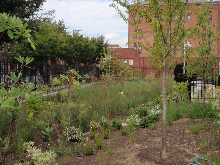
Biofiltration basins, often called rain gardens, use soil (typically engineered media or mixed soil) and native vegetation to capture runoff and remove pollutants. The media has a high infiltration rate but the underlying soil typically has a low infiltration rate (C or D soils). Therefore an underdrain is incorporated into the design. Water captured by the BMP is filtered through the engineered media and most of the treated water is captured by the underdrain and returned to the storm sewer system. Some water infiltrates below the underdrain and some water is taken up by plants. The amount of water that infiltrates can be maximized by raising the underdrain above the native soil or using an upturned elbow in the underdrain. Water captured by the BMP must drawdown within 48 hours.
For more information, see the following pages in this Manual.
- Bioretention terminology (including types of bioretention)
- Overview for bioretention
- Design criteria for bioretention
- Construction specifications for bioretention
- Operation and maintenance of bioretention
- Cost-benefit considerations for bioretention
- Calculating credits for bioretention
- Soil amendments to enhance phosphorus sorption
- Summary of permit requirements for bioretention
- Supporting material for bioretention
- External resources for bioretention
- References for bioretention
- Requirements, recommendations and information for using bioretention with no underdrain BMPs in the MIDS calculator
| Applications | Treatment capabilities2, 3 | ||
|---|---|---|---|
| Residential | Yes | TSS | High4 |
| Commercial | Yes | TN | Low/Medium |
| Ultra-urban | Limited6 | TP | Medium/high5 |
| Industrial | Yes1 | Chloride | Low |
| Highway/road | Yes | Metals | High |
| Recreational | Yes | Oils and grease | High |
| Pathogens | High | ||
| 1 Unless the filtration practice is located in an industrial area with exposed significant materials or from vehicle fuelling and maintenance areas. 2 This is only for the portion of flow that enters the filtration basin; by-passed runoff does not receive treatment; 3 Low = < 30%; Medium = 30-65%; High = 65 -100%); 4 Assumes adequate pretreatment; 5 Certain soil mixes can leach P; 6 Due to a size restriction Sources: EPA Factsheet, 1999; Davis et al., 2001, 2003, 2006; Hsieh and Davis, 2005; Hong et al., 2006; Hunt et al., 2006; NPRPD, 2007; Li and Davis, 2009; Diblasi et al., 2009; Passeport et al., 2009; Brown et at., 2011a, b; Komlos et al., 2012; Denich et al., 2013; Li and Davis, 2013; California Stormwater BMP |
|||
Permeable pavement (with an underdrain)
Permeable pavements are paving surfaces that allow stormwater runoff to filter through surface voids into an underlying stone reservoir for filtration and/or storage. They are suitable for driveways, trails, parking lots, and roadways with lighter traffic. The most commonly used permeable pavement surfaces are pervious concrete, porous asphalt, and permeable interlocking concrete pavers (PICP). All permeable pavements have a similar design layering system, consisting of a surface pavement layer, an underlying stone aggregate reservoir layer, optional underdrains for filtration and geotextile over non-compacted soil subgrade. Discharge of this stored runoff occurs primarily to underdrains, though some infiltration occurs into the underlying soil. The amount of water that infiltrates can be maximized by raising the underdrain above the native soil or using an upturned elbow in the underdrain. Water captured by the BMP must drawdown within 48 hours. The drainage area leading to permeable pavements should not exceed twice the surface area of the final pavement surface.
For more information, see the following pages in this Manual.
- Overview for permeable pavement
- Types of permeable pavement
- Design criteria for permeable pavement
- Construction specifications for permeable pavement
- Assessing the performance of permeable pavement
- Operation and maintenance of permeable pavement
- Calculating credits for permeable pavement
- Additional considerations for permeable pavement
- Links for permeable pavement
- References for permeable pavement
- Requirements, recommendations and information for using permeable pavement BMPs in the MIDS calculator
| Applications | Treatment capabilities2, 3 | ||
|---|---|---|---|
| Residential | Yes | TSS | High4 |
| Commercial | Yes | TN | Medium/High |
| Ultra-urban | Yes | Nitrate | Low/Medium |
| Industrial | Yes1 | TP | Medium/High |
| Retrofit | Yes | Chloride | Low |
| Highway/road | Yes | Metals | High |
| Recreational | Yes | Oils and grease | High |
| Pathogens | 5 | ||
|
1 Unless the filtration practice is located in an industrial area with exposed significant materials or from vehicle fuelling and maintenance areas. 2 This is only for the portion of flow that enters the filtration basin; by-passed runoff does not receive treatment; 3 Low = < 30%; Medium = 30-65%; High = 65 -100%); 4 Assumes adequate pretreatment; 5 Insufficient information Source: Schueler, 1987; Pratt et al, 1999; Adams, 2003; Brattebo and Booth, 2003; Adams, 2003; Bean et al, 2007; SEMCOG, 2008; International Stormwater Database, 2012 |
|||
Tree box/Tree trench (with an underdrain)
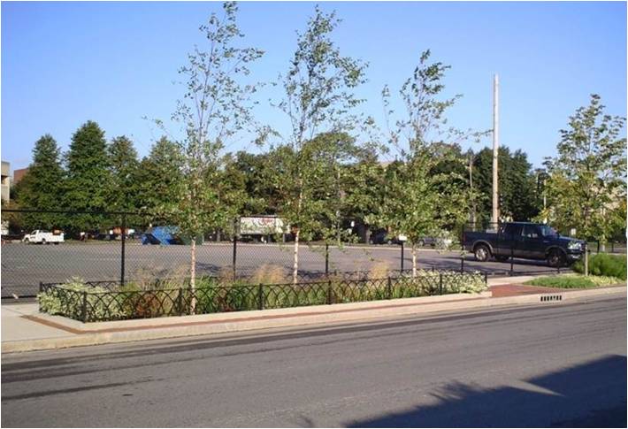
Tree trenches are a system of trees that are connected by an underground filtration structure. The system consists of a stormwater tree trench or box lined with geotextile fabric with structural stone, gravel or soil boxes in which the trees are placed. Tree systems consist of an engineered soil or rock layer designed to treat stormwater runoff via filtration through plant and soil/rock media, and through evapotranspiration from trees. Water that is filtered through the engineered media largely passes to an underdrain and is returned to the storm sewer system. Some infiltration occurs into the underlying soil. The amount of water that infiltrates can be maximized by raising the underdrain above the native soil or using an upturned elbow in the underdrain. Water captured by the BMP must drawdown within 48 hours. Tree species are carefully selected to survive both inundation and drought conditions in urban environments where they will be potentially affected by chloride and other traffic concerns. The drainage area to tree trenches and boxes should be less than five acres depending on the size of each trench. Irrigation, whether manual or automated, is strongly encouraged during the tree’s establishment period.
For more information, see the following pages in this Manual.
Trees - general
- Overview for trees
- Types of tree BMPs
- Plant lists for trees
- Street sweeping for trees
- References for trees
- Supporting material for trees
Tree boxes/tree trenches
- Design guidelines for tree quality and planting - tree trenches and tree boxes
- Design guidelines for soil characteristics - tree trenches and tree boxes
- Construction guidelines for tree trenches and tree boxes
- Protection of existing trees on construction sites
- Operation and maintenance of tree trenches and tree boxes
- Assessing the performance of tree trenches and tree boxes
- Calculating credits for tree trenches and tree boxes
- Case studies for tree trenches and tree boxes
- Soil amendments to enhance phosphorus sorption
- Fact sheet for tree trenches and tree boxes
- Requirements, recommendations and information for using trees as a BMP in the MIDS calculator
| Applications | Treatment capabilities2, 3 | ||
|---|---|---|---|
| Residential | Yes | TSS | High4 |
| Commercial | Yes | TN | Low/Medium |
| Ultra-urban | Yes | TP | Medium/High5 |
| Industrial | Yes1 | Chloride | Low |
| Highway/road | No | Metals | High |
| Recreational | Yes | Oils and grease | High |
| Pathogens | High | ||
|
1 Unless the filtration practice is located in an industrial area with exposed significant materials or from vehicle fuelling and maintenance areas. 2 This is only for the portion of flow that enters the filtration basin; by-passed runoff does not receive treatment; 3 Low = < 30%; Medium = 30-65%; High = 65 -100%); 4 Assumes adequate pretreatment; 5 Certain soil mixes can leach P. Source: see [1] |
|||
Dry swale and stormwater step-pool (with check dams and underdrains)
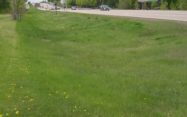
Similar to vegetated swales designed for stormwater conveyance, dry swales with underdrains are designed as linear, multi-celled stormwater filtration BMP’s. For high gradient conditions, stormwater step-pools can be utilized. By incorporating earthen or structural check dams, runoff is retained along a series of narrow, shallow basins or cells. This runoff is filtered through engineered media or soil and largely captured by an underdrain and returned to the storm sewer system. Some infiltration occurs into the underlying soil. The amount of water that infiltrates can be maximized by raising the underdrain above the native soil or using an upturned elbow in the underdrain. Water captured by the BMP must drawdown within 48 hours. Coarse vegetation such as decorative plantings or even turf grass slow runoff movement. This system is designed to move, store, and infiltrate runoff from impervious surfaces such as linear roadways or parking lots. Dry swales are best designed for sites under 5 acres in size.
For information on dry swales, see the following pages.
- Overview for dry swale (grass swale)
- Design criteria for dry swale (grass swale)
- Construction specifications for dry swale (grass swale)
- Operation and maintenance of dry swale (grass swale)
- Assessing the performance of dry swale (grass swale)
- Cost considerations
- Case studies for dry swale (grass swale)
- References for dry swale (grass swale)
- Requirements, recommendations and information for using dry swale (grass swale) without an underdrain in the MIDS calculator
- Requirements, recommendations and information for using dry swale (grass swale) with an underdrain in the MIDS calculator
- Requirements, recommendations and information for using swale side slope as a BMP in the MIDS calculator
For information on step pools, see the following pages.
- Terminology for high-gradient stormwater step-pool swale
- Overview for high-gradient stormwater step-pool swale
- Design criteria for high-gradient stormwater step-pool swale
- Construction specifications for high-gradient stormwater step-pool swale
- Operation and maintenance of high-gradient stormwater step-pool swale
- Assessing the performance of high-gradient stormwater step-pool swale
- Check dams for stormwater swales
- Plants for swales
- Cost considerations
- External resources for high-gradient stormwater step-pool swale
- References for high-gradient stormwater step-pool swale
| Applications | Treatment capabilities2, 3 | ||
|---|---|---|---|
| Residential | Yes | TSS | High4 |
| Commercial | Yes | TN | Low/Medium |
| Ultra-urban | Limited | TP | Low/Medium5 |
| Industrial | Yes1 | Chloride | Low |
| Highway/road | Yes | Metals | High |
| Recreational | Yes | Oils and grease | High |
| Pathogens | Medium | ||
| 1 Unless the filtration practice is located in an industrial area with exposed significant materials or from vehicle fuelling and maintenance areas. 2 This is only for the portion of flow that enters the filtration basin; by-passed runoff does not receive treatment; 3 Low = < 30%; Medium = 30-65%; High = 65 -100%); 4 Assumes adequate pretreatment; 5 Certain soil mixes can leach P. Source: see [2] |
|||
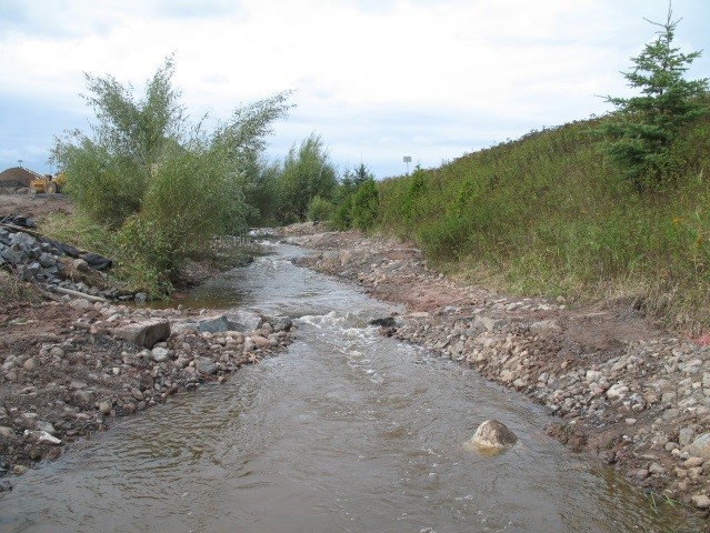
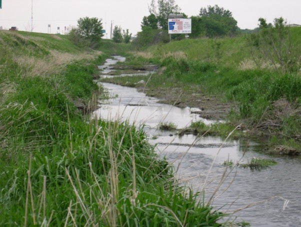
Wet swales
Wet swales occur when the water table is located very close to the surface or water does not readily drain out of the swale. A wet swale acts as a very long and linear shallow biofiltration treatment system. The entire water quality treatment volume is stored within a series of cells created by check dams. Cells may be planted with emergent wetland plant species to improve pollutant removal. Wet swales are commonly used for drainage areas less than 5 acres in size.
For more information, see the following pages in this manual.
- Overview for wet swale (wetland channel)
- Types of filtration
- Design criteria for wet swale (wetland channel)
- Construction specifications for wet swale (wetland channel)
- Operation and maintenance of wet swale (wetland channel)
- Assessing the performance of wet swale (wetland channel)
- Calculating credits for wet swale (wetland channel)
- External resources for wet swale (wetland channel)
- Requirements, recommendations and information for using wet swale in the MIDS calculator
- Requirements, recommendations and information for using swale side slope as a BMP in the MIDS calculator
| Applications | Treatment capabilities2, 3 | ||
|---|---|---|---|
| Residential | Yes | TSS | Medium4 |
| Commercial | Yes | TN | Low |
| Ultra-urban | Limited | TP | Low5 |
| Industrial | Yes1 | Metals | Low |
| Highway/road | Yes | Oil and grease | Low |
| Recreational | Yes | Pathogens | Low |
| Chloride | Low | ||
|
1 Unless the filtration practice is located in an industrial area with exposed significant materials or from vehicle fuelling and maintenance areas. 2 This is only for the portion of flow that enters the filtration basin; by-passed runoff does not receive treatment; 3 Low = < 30%; Medium = 30-65%; High = 65 -100%); 4 Assumes adequate pretreatment; 5 Certain soil mixes can leach P. Source: see [3] |
|||
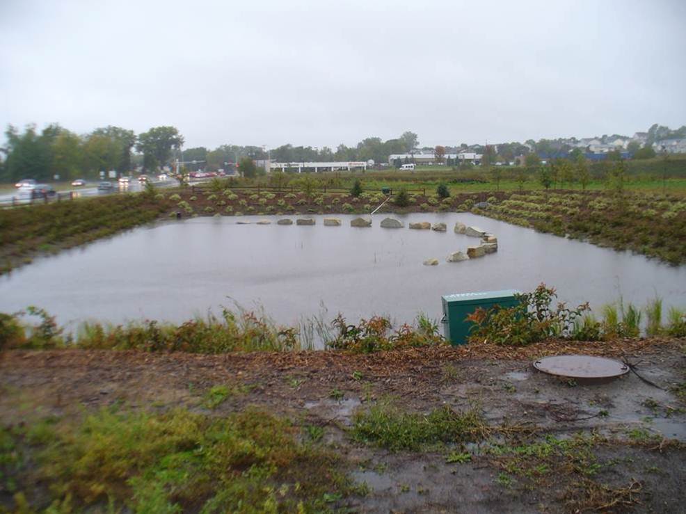
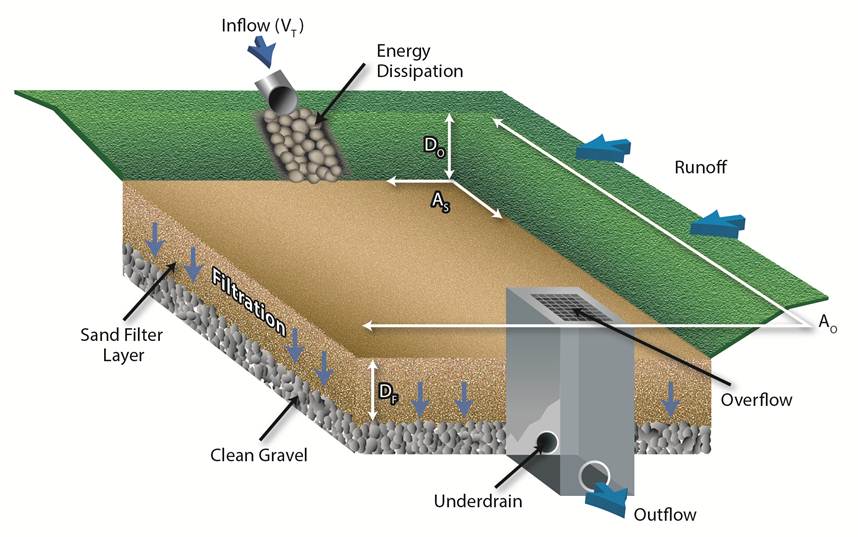
Media (sand) filter
Media filters treat stormwater through a variety of different filtering materials whose purpose is to remove pollution from runoff. Variants include surface sand filters, underground sand filters and perimeter sand filters. Most media filters have an underdrain and are effective at removing sediment and pollutants associated with sediment. Media filters may be enhanced with iron or other material to facilitate removal of dissolved pollutants, such as dissolved phosphorus.
For more information on media filters, see the following sections in the Minnesota Stormwater Manual.
- Overview for filtration
- Types of filtration
- Design criteria for filtration
- Construction specifications for filtration
- Assessing the performance of swales
- Assessing the performance of sand (media) filters
- Operation and maintenance of filtration
- Calculating credits for sand filter
- Cost-benefit considerations for filtration
- References for filtration
| Applications | Treatment capabilities2, 3 | ||
|---|---|---|---|
| Residential | Yes | TSS | High4 |
| Commercial | Yes | TN | Medium |
| Ultra-urban | Limited | TP | Medium |
| Industrial | Yes1 | Metals | Medium |
| Highway/road | Yes | Oil and grease | High |
| Recreational | Yes | Pathogens | High |
| Chloride | Low | ||
|
1 Unless the filtration practice is located in an industrial area with exposed significant materials or from vehicle fuelling and maintenance areas. 2 This is only for the portion of flow that enters the filtration basin; by-passed runoff does not receive treatment; 3 Low = < 30%; Medium = 30-65%; High = 65 -100%); 4 Assumes adequate pretreatment. Source: see [4] |
|||
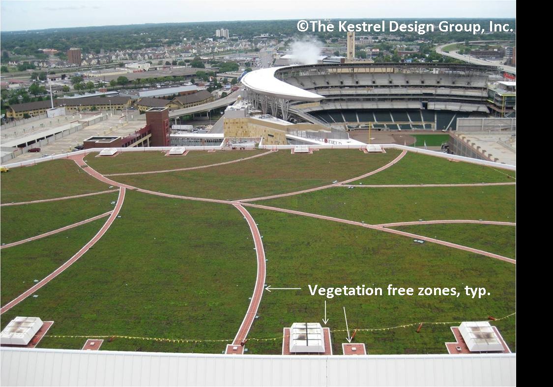
Green roofs
Green roofs typically occur at the beginning of stormwater treatment trains. Green roofs provide filtering of suspended solids and pollutants associated with those solids, although total suspended solid (TSS) concentrations from traditional roofs are generally low. Green roofs provide both volume and rate control, thus decreasing the stormwater volume being delivered to downstream Best Management Practices (BMPs).
For more information, see the following pages in this manual.
- Overview for green roofs
- Types of green roofs
- Design criteria for green roofs
- Construction specifications for green roofs
- Assessing the performance of green roofs
- Operation and maintenance (O&M) of green roofs
- Calculating credits for green roofs
- Cost-benefit considerations for green roofs
- Plant lists for green roofs
- Links for green roofs
- References for green roofs
- Supporting material for green roofs
- Green roofs terminology and glossary
- Green roof fact sheet
- Requirements, recommendations and information for using green roofs as a BMP in the MIDS calculator
| Applications | Treatment capabilities1 | ||
|---|---|---|---|
| Residential | Yes | TSS | Medium |
| Commercial | Yes | TN | Low |
| Ultra-urban | Yes | TP | Low2 |
| Industrial | Yes | Metals | Low |
| Highway/road | No | Oil and grease | Low |
| Recreational | No | Pathogens | Low |
| Chloride | Low | ||
| 1 Low = < 30%; Medium = 30-65%; High = 65 -100%); 2 Certain soil mixes can leach P. | |||
Practices with a raised underdrain or internal water storage
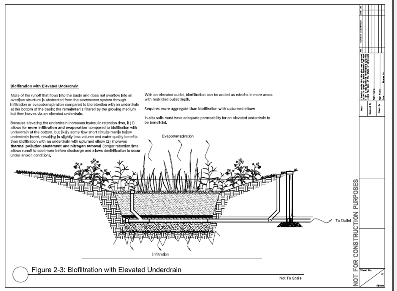
A filtration practice with a raised underdrain provides a storage area below the invert of the underdrain discharge pipe. This area provides a recharge zone and quantity control can also be augmented with this storage area. The storage area is equal to the void space of the material used. Since the practice utilizes both infiltration and an underdrain, considerations include those for both infiltration practices and filtration with an underdrain at the bottom. These include an assessment of infiltration constraints and media.
A filtration practice with internal water storage is not commonly used in the Midwestern United States but is widely used in some places on the east coast, such as North Carolina. The use of an upturned elbow in this practice allows water to be retained within the practice, leading to increased pollutant removal, increased infiltration, and increased evapotranspiration. The practice is particularly effective at removing nitrogen through denitrification. The media should be 3 feet or more thick to allow water to be drawn down below the root zone. Underlying soils should be permeable enough to allow water stored within the practice to infiltrate. Hunt provides an overview of this practice.
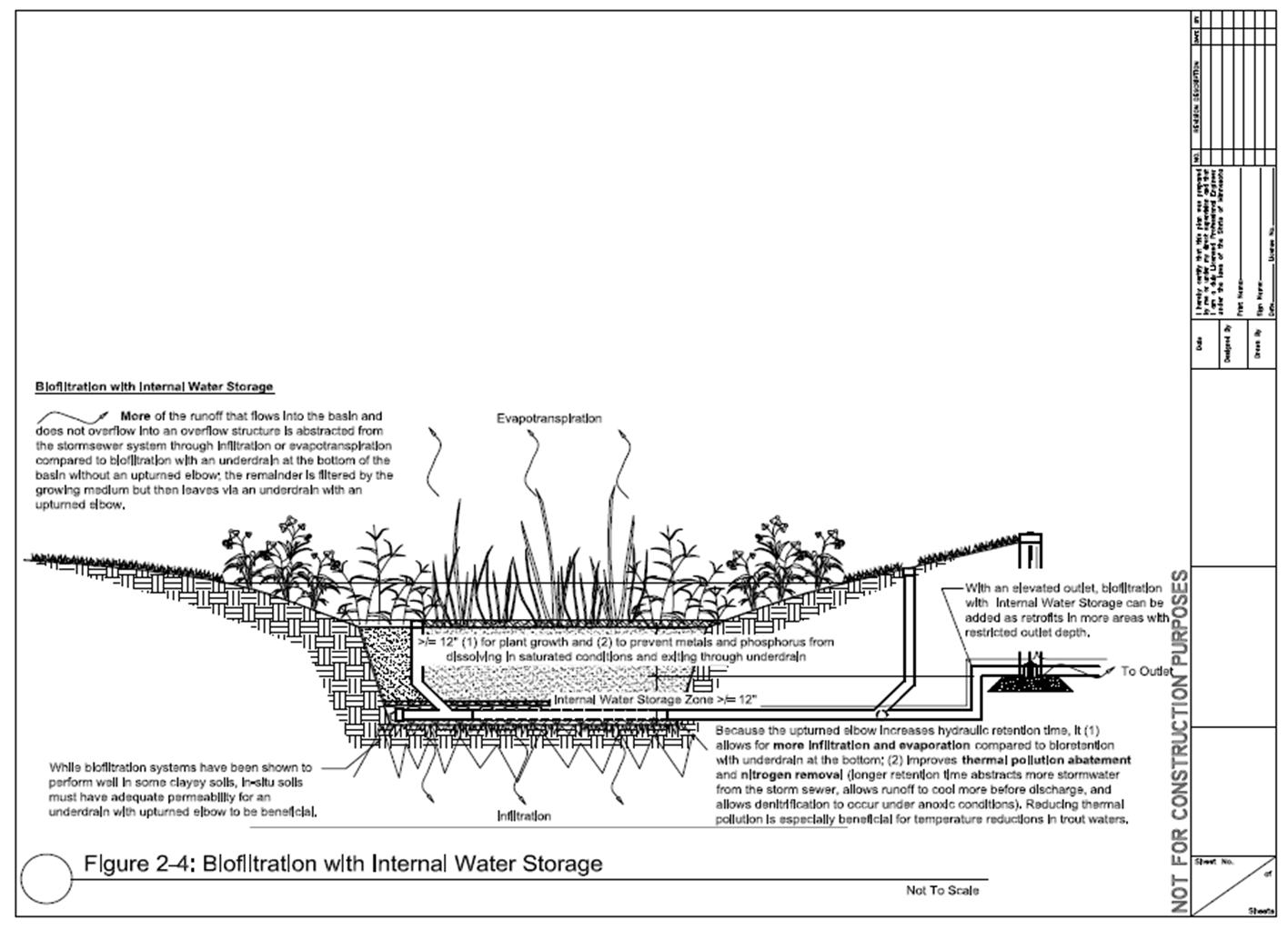
Raising an underdrain or utilizing internal water storage enhances infiltration, but the practice still functions as a filtration practice. Pollutant removal for the infiltrated portion is 100 percent. We conducted simple calculations utilizing the Minimal Impact Design Standards (MIDS) calculator to illustrate the effect of a raised underdrain on volume and pollutant removal. The following inputs were used in the analysis.
- Site zip code = 55155
- 1 acre of impervious and 1 acre of pervious managed turf
- Biofiltration with a raised underdrain, sized to hold the MIDS performance goal of 1.1 inches
- Basin dimensions 3993 square feet by 1 foot ponding depth
- Media Mix C (low phosphorus media)
- 3 feet of media
- Underlying soil = Hydrologic Soil Group C
- Three scenarios
- Underdrain at bottom
- Underdrain raised 0.5 feet
- Underdrain raised 0.8 feet (Note: this is the maximum depth below the underdrain to meet the 48 hour drawdown requirement)
Results of the analysis are summarized below.
- Underdrain at bottom: 27% of performance goal achieved; 45% annual volume removal; 74% annual total phosphorus removed; 89% annual TSS removed
- Underdrain raised 0.5 feet: 39% of performance goal achieved; 58% annual volume removal; 80% annual total phosphorus removed; 92% annual TSS removed
- Underdrain raised 0.8 feet: 47% of performance goal achieved; 64% annual volume removal; 83% annual total phosphorus removed; 93% annual TSS removed
The analysis indicates significant increase in volume retained, moderate increase in phosphorus retention, and a small increase in TSS retention.
Unit processes for different filtration BMPs
The following table provides a summary of unit processes for the different filtration BMPs.
| Control | Dry swale or step pool | Wet swale | Biofiltration | Permeable pavement | Tree box/tree trench | Green roof |
|---|---|---|---|---|---|---|
| Peak flow attenuation | X | X | X | X | X | |
| Runoff volume reduction | X | X | X | X | X | |
| Infiltration | X | X | X | X | ||
| Dispersion | X | |||||
| Evapotranspiration | X | X | X | X | X | |
| Runoff collection and usage | X | X | ||||
| Sedimentation | X | X | X | |||
| Flotation | X | |||||
| Laminar separation | ||||||
| Swirl concentration | ||||||
| Sorption | X | X | X | X | X | |
| Precipitation | X | X | ||||
| Coagulation | X | X | ||||
| Filtration | X | X | X | X | X | X |
| Plant metabolism | X | X | X | |||
| Nitrification/denitrification | X | X | ||||
| Organic compound degradation | X | X | X | X | X | |
| Pathogen die off | X | |||||
| Temperature reduction | X | X | X | X | X | |
| Disinfection | X | X |
Information tables
The following tables describe and differentiate different characteristics of stormwater filtration BMPs.
Overview table
The following table provides a brief description and schematic of each stormwater filtration BMP.
| Stormwater BMP | General Overview | Illustration |
|---|---|---|
| Dry swale or step pool | Dry swales, sometimes called grass swales, are similar to bioretention cells but are configured as shallow, linear channels. Dry swales function primarily as a conveyance BMP but may incorporate check dams into the design, thus allowing water to be stored behind the check dam and filtered through the underlying soil or media. Discharge of filtered runoff occurs primarily through an underdrain, though some infiltration into the underlying soil occurs below the underdrain. | 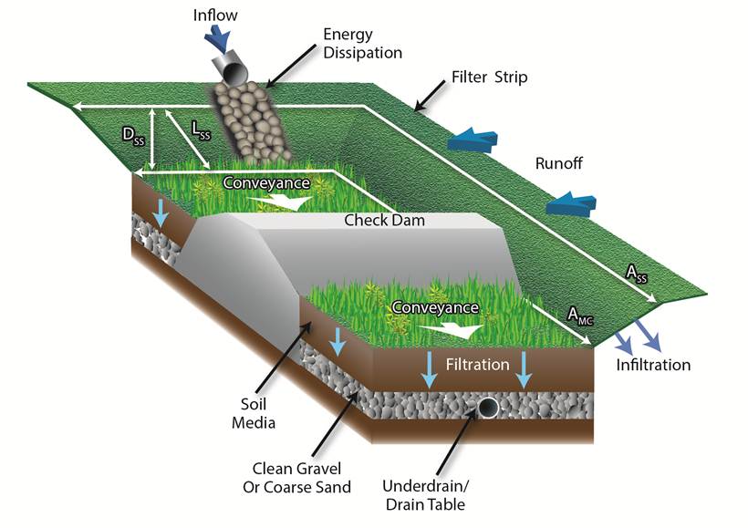
|
| Wet swale | Wet swales act as very long and linear shallow biofiltration or linear wetland treatment systems. Wet swales do not provide volume reduction and have limited treatment capability. Incorporation of check dams into the design allows treatment of a portion or all of the water quality volume within a series of cells created by the check dams. |  |
| Biofiltration Basin | Often called rain gardens, biofiltration basins use engineered or mixed soils and plantings to capture and filter runoff. Discharge of filtered runoff occurs primarily through an underdrain, though some infiltration into the underlying soil occurs below the underdrain. | 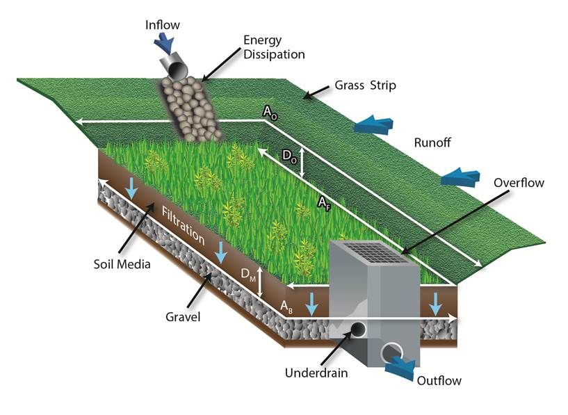 |
| Permeable pavement with underdrain | Permeable pavements are paving surfaces that allow stormwater runoff to filter through surface voids into an underlying stone reservoir. The most commonly used permeable pavement surfaces are pervious concrete, porous asphalt, and permeable interlocking concrete pavers (PICP). All permeable pavements have a similar structure, consisting of a surface pavement layer, an underlying stone aggregate reservoir layer, optional underdrains and geotextile over uncompacted soil subgrade. Discharge of this stored runoff occurs primarily through an underdrain, though some infiltration into the underlying soil occurs below the underdrain. | |
| Tree Trench/Tree Box (with underdrain) | A system of trees that are connected by an underground storage structure. The system consists of a trench lined with geotextile fabric with structural stone, gravel or soil boxes in which the trees are placed. Tree systems consist of an engineered soil layer designed to treat stormwater runoff via filtration through plant and soil media, and through evapotranspiration from trees. Discharge of filtered runoff occurs primarily through an underdrain, though some infiltration into the underlying soil occurs below the underdrain. |  |
| Media filter (sand filter) | Runoff is captured and stored in a filter media consisting of a sand filter bed (~18 inches), with temporary runoff storage above the bed. Pollutants are trapped or strained out at the surface of the filter bed. Discharge of filtered runoff occurs primarily through an underdrain. |
|
| Green roof | Green roofs consist of a a layer or layers of media that filter suspended solids and pollutants associated with those solids. Water passes through the media to an underlying impermeable layer that conveys the filtered water from the roof. |  |
Contributing drainage area table
The following table provides a summary of recommended contributing drainage area for each stormwater filtration BMP.
Contributing drainage area is defined as the total area, including pervious and impervious surfaces, contributing to a best management practice (BMP). It is assumed that in most cases, with the exception of green roofs and many permeable pavement systems, impervious surfaces will constitute more than 50 percent of the contributing area to the BMP and that most of this impervious is directly connected impervious. The recommended contributing area to a BMP may be modified for the following conditions.
- The recommended contributing area may be increased if pervious surfaces constitute the majority of the contributing area and soils are hydrologic soil group (HSG) A or B
- The recommended contributing area should be decreased if impervious surfaces contribute more than 80 percent of the contributing area or if the entire impervious surface is directly connected and routed to the BMP
- The recommended contributing area should be decreased or may be increased based on pollutant loading (decrease with higher pollutant loads)
Runoff coefficients may be calculated for an area contributing to a BMP. Runoff coefficients greater than about 0.55 are typical of urban areas having 50 percent or more impervious surface. Typical runoff coefficients are shown on these pages ([5], [6]) and discussed here. To see how runoff curve number is associated with impervious percentages, see at this link.
| Stormwater BMP | Recommended contributing area | Notes |
|---|---|---|
| Dry swale or step pool | 5 acres or less | A dry swale or step pool must be able to drawdown within 48-hours in order to preserve vegetation. |
| Wet swale | 5 acres or less | The boundary between upland and wetland type vegetation should be considered in the design. Different plant species will be tolerant of different periods of inundation. |
| Biofiltration Basin | 5 acres or less | Biofiltration basins must meet the required 48 hour drawdown time and must be sized in order to allow for adequate maintenance. It is HIGHLY RECOMMENDED that biofiltration basins be designed to prevent high levels of bounce as submerging vegetation may inhibit plant growth. A maximum wet storage depth of 1.5 feet is HIGHLY RECOMMENDED. |
| Permeable Pavement (with underdrain) | It is RECOMMENDED that external contributing drainage area not exceed the surface area of the permeable pavement. It is HIGHLY RECOMMENDED that external contributing drainage area not exceed twice the surface area of the permeable pavement | It is RECOMMENDED that external drainage area be as close to 100% impervious as possible. Field experience has shown that drainage area (pervious or impervious) can contribute particulates to the permeable pavement and lead to clogging. Therefore, sediment source control and/or pretreatment should be used to control sediment run-on to the permeable pavement section. |
| Tree Trench/Tree Box (with underdrain) | up to 0.25 acres per tree | |
| Green roof | Not applicable | Contributing drainage from conventional roofs must be no larger than the surface area of the green roof |
| References: Virginia, North Carolina, West Virginia, Maine, Lake Tahoe, Connecticut, Massachusetts, New York, Wisconsin, Vermont, New Hampshire, Ontario, Pennsylvania | ||
Treatment properties table
The following table provides information on pollutant removal mechanism(s), location in the stormwater treatment train, general pollutant removal, and potential applications for each of the stormwater BMPs.
| Stormwater BMP | Illustration | Pollutant Removal Mechanism | Location in Treatment Train | Pollutant Removal 1 | Potential Application |
|---|---|---|---|---|---|
| Dry swale or step pool |
|
Sedimentation / Infiltration | Throughout |
TSS: Medium TN: Low TP: Medium Chloride: Low Metals: Medium Oils and Grease: Low Pathogens: Low |
Residential Commercial Industrial Highway/Road Recreational |
| Wet swale | |
Sedimentation / Transpiration | Throughout |
TSS: Medium TN: Low TP: Low Chloride: Low Metals: Low Oils and Grease: Low Pathogens: Low |
Residential Commercial Industrial Highway/Road Recreation |
| Biofiltration Basin | |
Sedimentation / Filtration | Beginning |
TSS: High TN: Low/Medium TP: Medium/High2 Chloride: Low Metals: High Oils and Grease: High |
Residential Commercial Retrofit |
| Permeable pavement with underdrain | Filtration | Beginning |
TSS: High TN: Medium/High TP: Medium/High Chloride: Low Metals: High Oils and Grease: High |
Residential Commercial Ultra Urban Retrofit |
|
| Tree Trench/Tree Box (with underdrain) | |
Filtration, Transpiration | Throughout |
TSS: High TN: Medium/High TP: Medium/High Chloride: Low Metals: High Oils and Grease: High Pathogens: High |
Commercial Ultra Urban Retrofit |
| Media filter (sand filter) |
|
Filtration | Throughout |
TSS: High TN: Medium TP: Medium/High Chloride: Low Metals: Medium/High Oils and Grease: High Pathogens: High |
Residential Commercial Industrial Recreation |
| Green roof | |
Filtration | Throughout |
TSS: High TN: Low TP: Low Chloride: Low Metals: High Oils and Grease: High Pathogens: High |
Residential Commercial Ultra Urban Industrial Retrofit |
| 12 Low = < 30%; Medium = 30‐65%; High = 65‐100% 2Some media mixes can leach phosphorus. |
|||||
Selection considerations table
The following table provides information on general cost, maintenance requirements, pretreatment needs, and habitat quality for each of the stormwater filtration BMPs.
| Stormwater BMP | Illustration | Cost | Maintenance Requirements 3 | Space needed | Pretreatment 4 | Habitat Quality 5 |
|---|---|---|---|---|---|---|
| Dry swale or wet pool |
|
Low to medium (depends on components) | Simple‐Intensive | Small | Oil/Water Separator Sediment Basin (depending on watershed soil types, contributing drainage area, and potential for system fouling/plugging) | Low |
| Wet pool | |
Low | Simple | Small | Oil/Water Separator | Low |
| Biofiltration Basin | |
Low $0.5‐$1.3 CF | Simple‐Intensive | Small to medium | Needed Oil/Water Separator, Vegetated Filter, Sediment Basin, Water Quality Inlets | Medium‐High |
| Permeable Pavement (with underdrain) | Medium 3‐10 CF | Medium | Small to medium | No Pretreatment Required | None | |
| Tree Trench/Tree Box (with underdrain) |
High $1.80 ‐ $12.70 CF based on recommended soil volume of 1,414 CF per tree |
Intensive | Small to large | Needed Oil/Water Separator, Water Quality Inlets | Medium | |
| Media filter (sand filter) |
|
Low | Simple-moderate | Small | Needed Oil/Water Separator, Vegetated Filter, Sediment Basin | Low |
| Green roof | |
High | Moderate-intensive | Small | Low | Medium |
| 1 Maintenance requirements to be addressed and updated in future section 2 Pretreatment requirements to be revised as per updated section 3 Habitat quality refers to the possible diversity of plantings commonly installed with each BMP |
||||||
Infiltration Summary Table
To see all information contained in the previous tables in a single table, click on the following link: Filtration Summary Table
Related pages
The following practices typically employ an underdrain, which captures most of the runoff that enters the BMP. For information on these BMPs with no underdrain, see Stormwater infiltration Best Management Practices.
- Permeable pavement
- Trees
- Bioretention - biofiltration
- Swale
- Sand filter
- Iron enhanced sand filter (Minnesota Filter)
Other filtration BMPs, including pre-treatment practices
Manufactured devices