Green Infrastructure: Infiltration practices can be an important tool for retention and detention of stormwater runoff and treatment of pollutants in stormwater runoff. If the practice utilizes vegetation, additional benefits may include cleaner air, carbon sequestration, improved biological habitat, and aesthetic value.
Green Infrastructure: Infiltration of stormwater, where appropriate, is a preferred practice for managing stormwater runoff, as it reduces pollutants reaching receiving waters and retains water on the landscape
Best management practices that infiltrate stormwater runoff into underlying soil include, but are not limited, to
- infiltration basins,
- infiltration trenches (includes dry wells),
- underground infiltration systems,
- bioinfiltration,
- permeable pavements,
- tree trenches and tree boxes, and
- dry swale with check dams.
These are discussed briefly below. Additional information about these BMPs can be found in the following tables.
- Stormwater infiltration BMPs - overview
- Stormwater infiltration BMPs – selection considerations
- Stormwater infiltration BMPs - treatment properties
Information: Note that other practices may infiltrate water but are not specifically designed to infiltrate water at the point where water is detained. Examples include stormwater harvest and reuse systems, vegetated filter strips and swales without check dams.
Contents
- Infiltration basin
- Infiltration trench
- Bioinfiltration basin
- Permeable pavement
- Tree box/Tree trench
- Dry swale with check dams
- High gradient stormwater step-pool swale with check dams
- Non-structural infiltration practices
- Unit processes for different infiltration BMPs
- Information tables
- Related pages for stormwater infiltration
- Related pages for infiltration BMPs
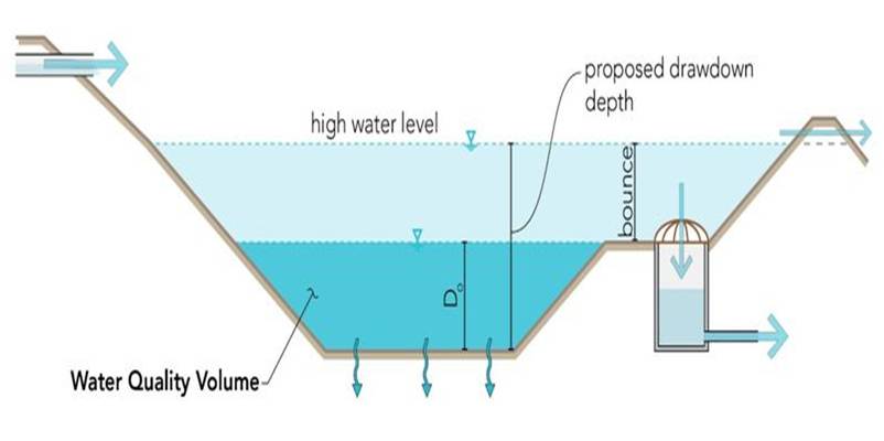
Infiltration basin
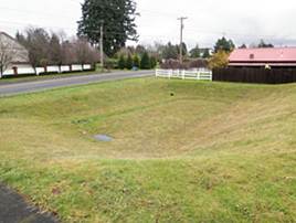
An infiltration basin is a natural or constructed impoundment that captures, temporarily stores and infiltrates the design volume of water (Water Quality Volume). Drawdown of this stored runoff occurs through infiltration into the surrounding naturally permeable soil. The required drawdown time is 48 hours or less. Water that is stored but not infiltrated must leave the bmp, typically through an outlet, within the required drawdown time. In the case of a constructed basin, the impoundment is created by excavation or embankment. Infiltration basins are commonly used for drainage areas of 5 to 50 acres with land slopes that are less than 20 percent. Typical depths range from 2 to 6 feet, including bounce in the basin. The sizing is to control stormwater volumes at the regional or development scale as opposed to bioretention basins (rain gardens) that are designed at the site scale. Typical dimensions range from 1,000 square feet up to an acre. Infiltration basins are commonly constructed with plant species that can tolerate and thrive in this unique growing environment.
For more information, see the following pages in this Manual.
- Overview for infiltration
- Design criteria for infiltration
- Construction specifications for infiltration
- Operation and maintenance of stormwater infiltration practices
- Cost-benefit considerations for infiltration
- Calculating credits for infiltration
- External resources for infiltration
- References for infiltration
- Requirements, recommendations and information for using infiltration basin/underground infiltration BMPs in the MIDS calculator
| Applications | Treatment capabilities3, 4, 5 | ||
|---|---|---|---|
| Residential | Yes | TSS | High6 |
| Commercial | Yes | TN | Medium/high |
| Ultra-urban | Limited1 | TP | Medium/high |
| Industrial | Yes2 | Chloride | Low |
| Highway/road | Limited | Metals | High |
| Recreational | Yes | Oils and grease | High |
| Pathogens | High | ||
| 1Due to a size restriction; 2Unless the infiltration practice is located in an industrial area with exposed significant materials or from vehicle fueling and maintenance areas. Infiltration BMPs are PROHIBITED in these areas; 3Underground infiltration systems may have different (likely lower) pollutant removal capabilities than what is provided in this table. These systems may have a wider application range. 4 This is only for the portion of flow that enters the infiltration basin; by-passed runoff does not receive treatment; 5Low = < 30%; Medium = 30-65%; High = 65 -100%); 6Assumes adequate pre-treatment. Sources: Schueler, 1987, 1992; USEPA 1993a, 1993b; Maniquiz et al., 2010; NPRPD, 2007; California Stormwater Manual, 2009; Pennsylvania Stormwater Manual, 2006. | |||
Infiltration trench

An infiltration trench is a shallow excavated trench, typically 3 to 6 feet deep, that is backfilled with a coarse stone aggregate allowing for the temporary storage of runoff in the void space of the material. Drawdown of this stored runoff occurs through infiltration into the surrounding naturally permeable soil. Infiltration trenches may be modified to become stormwater tree trenches and boxes where applicable with the addition of growing medium. All water captured by the BMP must be removed within 48 hours through infiltration and/or a drain. Trenches are commonly used for drainage areas less than 5 acres in size.
Caution: To avoid an infiltration trench being classified as a Class V injection well, it is strongly recommended that the length of the trench be at least 2 times greater than the depth of the trench.
For more information, see the following pages in this Manual.
- Overview for infiltration
- Design criteria for infiltration
- Construction specifications for infiltration
- Operation and maintenance of stormwater infiltration practices
- Cost-benefit considerations for infiltration
- Calculating credits for infiltration
- External resources for infiltration
- References for infiltration
- Requirements, recommendations and information for using infiltration basin/underground infiltration BMPs in the MIDS calculator
Dry wells (a.k.a. infiltration tubes, french drains, soak-away pits or soak holes)
A dry well or soak away pit is a smaller variation of an infiltration trench. It is a subsurface storage facility (a structural chamber or an excavated pit backfilled with a coarse stone aggregate) that receives and temporarily stores stormwater runoff. Discharge of this stored runoff occurs through infiltration into the surrounding naturally permeable soil. Due to their size, dry wells are typically designed to handle stormwater runoff from smaller drainage areas, less than one acre in size (e.g. roof tops).
For more information, see the following pages in this Manual.
- Overview for infiltration
- Design criteria for infiltration
- Construction specifications for infiltration
- Operation and maintenance of stormwater infiltration practices
- Cost-benefit considerations for infiltration
- Calculating credits for infiltration
- External resources for infiltration
- References for infiltration
- Requirements, recommendations and information for using infiltration basin/underground infiltration BMPs in the MIDS calculator
Underground infiltration systems
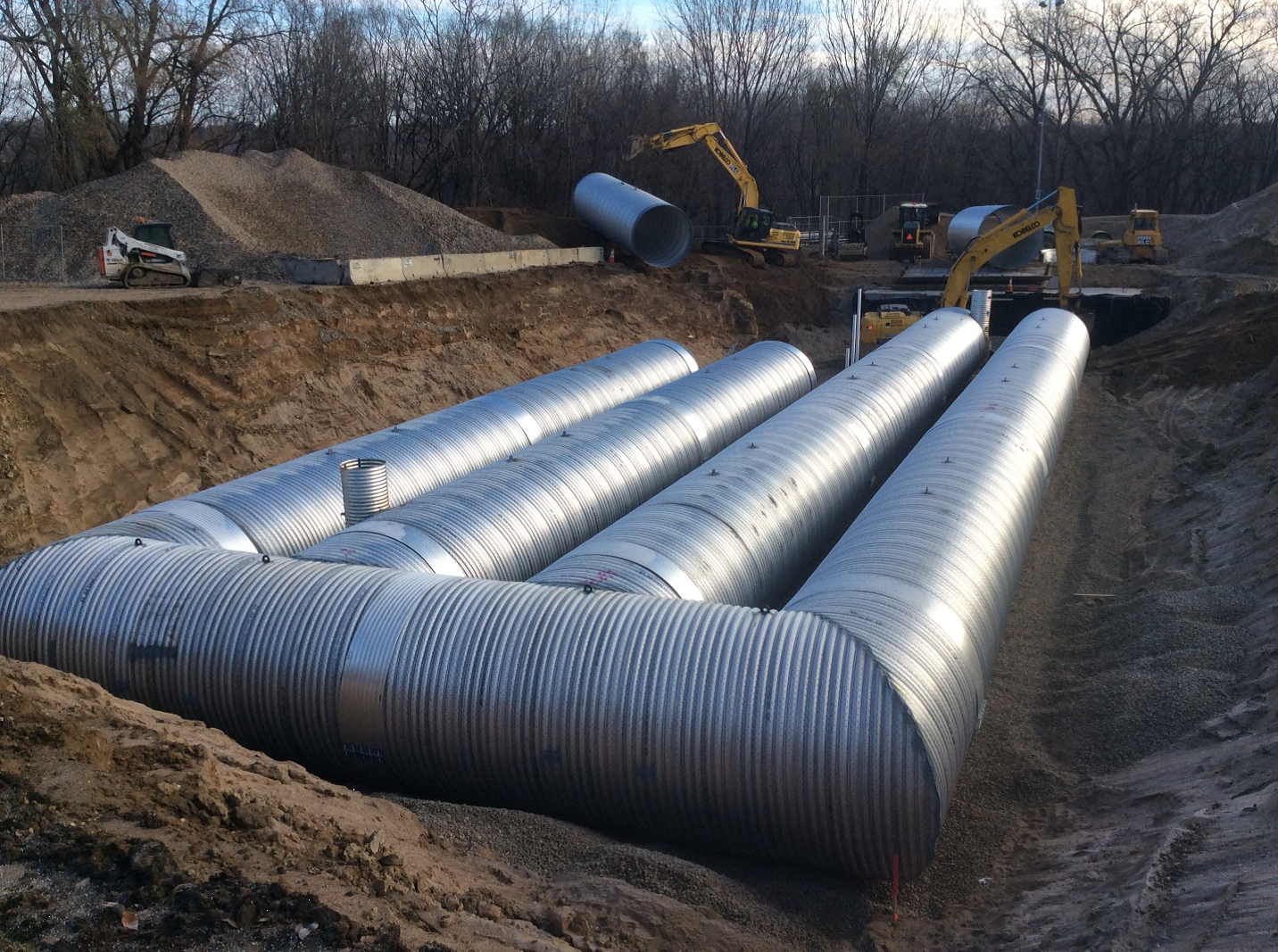
Several underground infiltration systems, including pre-manufactured pipes, vaults, and modular structures, have been developed as alternatives to infiltration basins and trenches for space-limited sites and stormwater retrofit applications. Underground infiltration systems are occasionally the only stormwater BMP options on fully developed sites or highly urban and ultra-urban environments as they can be located under other land uses such as parking lots or play areas. These systems are similar to infiltration basins and trenches in that they are designed to capture, temporarily store and infiltrate the design volume of stormwater over several days. Underground infiltration systems are generally applicable to small development sites (typically less than 10 acres) and should be installed in areas that are easily accessible to routine and non-routine maintenance. These systems should not be located in areas or below structures that cannot be excavated in the event that the system needs to be replaced or invasive maintenance is required to maintain performance.
Underground infiltration systems and dry wells have been installed below parking lots and other impervious surfaces on sites where insufficient space exists for a surface infiltration system. They are designed to temporarily store stormwater runoff before slowly infiltrating the water into the subsurface (Connecticut, 2004). There is limited information on the effectiveness of these systems in removing pollutants.
One concern is that underground infiltration may meet the U.S. Environmental Protection Agency (EPA) definition of a Class V injection well. Class V injection wells are defined as any bored, drilled, or driven shaft, or any dug hole that is deeper than its widest surface dimension. Class V injection wells can also be an improved sinkhole, or a subsurface fluid distribution system (from U.S. EPA, June 2003). The U.S. EPA administers Class V injection well permits in Minnesota. Minimum requirements for installing, permitting, and operating a Class V well is defined by the USEPA.
A second concern pertains to the overall pollutant removal effectiveness of those underground infiltration systems that do not meet the definition of a Class V injection well. The document released by the Transport Research Synthesis titled “Issues of Concern Related to Underground Infiltration Systems for Stormwater Management and Treatment” provides a good overview of the concerns related to underground infiltration systems (MNDOT, 2009). Issues identified in this report include the following.
- There is potential that an underground infiltration system meets the criteria of a Class V injection well.
- There is insufficient knowledge of the fate of pollutants in the subgrade below the buried infiltration systems.
- Roadways and parking lots with high volumes of traffic have higher concentrations of certain pollutants, including heavy metals and PAHs.
- Underground systems do not allow for the pollutant removal that is accomplished through biological activity and vegetation uptake.
- The minimum separation requirement of 3 feet between the bottom of the infiltration system and the seasonally high groundwater elevation may be insufficient for adequate pollutant removal. Additional study is recommended.
- Maintenance of underground systems is critical for effective pollutant removal. However, access for maintenance is challenging. There are concerns that the difficult access is preventing owners from properly maintaining these systems.
For more information, see the following pages in this Manual.
- Overview for infiltration
- Design criteria for infiltration
- Construction specifications for infiltration
- Operation and maintenance of stormwater infiltration practices
- Cost-benefit considerations for infiltration
- Calculating credits for infiltration
- External resources for infiltration
- References for infiltration
- Requirements, recommendations and information for using infiltration basin/underground infiltration BMPs in the MIDS calculator
| Applications | Treatment capabilities3, 4 | ||
|---|---|---|---|
| Residential | Yes | TSS5 | High5 |
| Commercial | Yes | TN | Medium/high |
| Ultra-urban | Yes | TP | Medium/high |
| Industrial | Yes1 | Chloride | Low |
| Highway/road | 2 | Metals | High |
| Recreational | Yes | Oils and grease | High |
| Pathogens | High | ||
| 1Unless the infiltration practice is located in an industrial area with exposed significant materials or from vehicle fuelling and maintenance areas. Infiltration BMPs are PROHIBITED in these areas; 2Yes for infiltration trench, limited for underground infiltration, no for dry well; 3This is only for the portion of flow that enters the infiltration basin; by-passed runoff does not receive treatment; 4Low = < 30%; Medium = 30-65%; High = 65 -100%); 5Assumes adequate pre-treatment Sources: Schueler, 1987, 1992; USEPA 1993a, 1993b; Maniquiz et al., 2010; NPRPD, 2007; California Stormwater Manual, 2009; Pennsylvania Stormwater Manual, 2006 | |||
Bioinfiltration basin
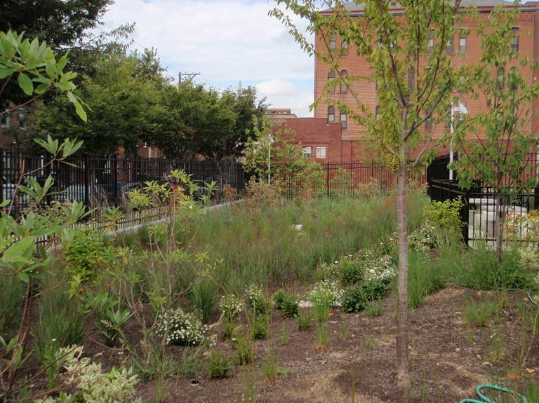
Bioinfiltration basins, often called rain gardens, use soil (typically engineered media or mixed soil) and native vegetation to capture runoff and remove pollutants. Both the media and underlying soil typically have high infiltration rates that allow captured water to infiltrate within a required drawdown time, usually 48 hours. Bioinfiltration systems, which lack an underdrain and are designed for infiltration, differ from biofiltration systems, which have an underdrain and are designed primarily for filtration. For more information, see the following pages in this Manual.
- Bioretention terminology (including types of bioretention)
- Overview for bioretention
- Design criteria for bioretention
- Construction specifications for bioretention
- Operation and maintenance of bioretention
- Cost-benefit considerations for bioretention
- Calculating credits for bioretention
- Soil amendments to enhance phosphorus sorption
- Summary of permit requirements for bioretention
- Supporting material for bioretention
- External resources for bioretention
- References for bioretention
- Requirements, recommendations and information for using bioretention with no underdrain BMPs in the MIDS calculator
| Applications | Treatment capabilities2, 3 | ||
|---|---|---|---|
| Residential | Yes | TSS | High4 |
| Commercial | Yes | TN | Low/Medium5 |
| Ultra-urban | Limited7 | TP | Medium/high6 |
| Industrial | Yes1 | Chloride | Low |
| Highway/road | Yes | Metals | High |
| Recreational | Yes | Oils and grease | High |
| Pathogens | High | ||
| 1Unless the infiltration practice is located in an industrial area with exposed significant materials or from vehicle fuelling and maintenance areas. Infiltration BMPs are PROHIBITED in these areas; 2This is only for the portion of flow that enters the infiltration basin; by-passed runoff does not receive treatment; 3 Low = < 30%; Medium = 30-65%; High = 65 -100%); 4Assumes adequate pre-treatment; 5This assumes no underdrain; 6 Certain soil mixes can leach P; 7 Due to a size restriction Sources: EPA Factsheet, 1999; Davis et al., 2001, 2003, 2006; Hsieh and Davis, 2005; Hong et al., 2006; Hunt et al., 2006; NPRPD, 2007; Li and Davis, 2009; Diblasi et al., 2009; Passeport et al., 2009; Brown et at., 2011a, b; Komlos et al., 2012; Denich et al., 2013; Li and Davis, 2013; California Stormwater BMP | |||
Permeable pavement
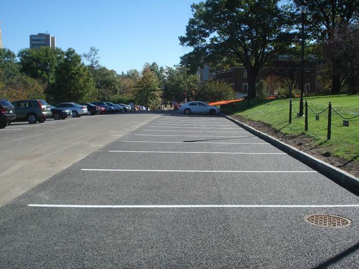
Permeable pavements are paving surfaces that allow stormwater runoff to filter through surface voids into an underlying stone reservoir for infiltration and/or storage. They are suitable for driveways, trails, parking lots, and roadways with lighter traffic. The most commonly used permeable pavement surfaces are pervious concrete, porous asphalt, and permeable interlocking concrete pavers (PICP). All permeable pavements have a similar design layering system, consisting of a surface pavement layer, an underlying stone aggregate reservoir layer, optional underdrains for filtration and geotextile over non-compacted soil subgrade. Discharge of this stored runoff occurs through infiltration into the surrounding naturally permeable soil. The drainage area leading to permeable pavements should not exceed twice the surface area of the final pavement surface.
For more information, see the following pages in this Manual.
- Overview for permeable pavement
- Types of permeable pavement
- Design criteria for permeable pavement
- Construction specifications for permeable pavement
- Assessing the performance of permeable pavement
- Operation and maintenance of permeable pavement
- Calculating credits for permeable pavement
- Additional considerations for permeable pavement
- Links for permeable pavement
- References for permeable pavement
- Requirements, recommendations and information for using permeable pavement BMPs in the MIDS calculator
| Applications | Treatment capabilities2, 3 | ||
|---|---|---|---|
| Residential | Yes | TSS | High4 |
| Commercial | Yes | TN | Medium/High |
| Ultra-urban | Yes | Nitrate | Low/Medium |
| Industrial | Yes1 | TP | Medium/High |
| Retrofit | Yes | Chloride | Low |
| Highway/road | Yes | Metals | High |
| Recreational | Yes | Oils and grease | High |
| Pathogens | 5 | ||
| 1Unless the infiltration practice is located in an industrial area with exposed significant materials or from vehicle fuelling and maintenance areas. Infiltration BMPs are PROHIBITED in these areas; 2This is only for the portion of flow that enters the infiltration basin; by-passed runoff does not receive treatment; 3Low = < 30%; Medium = 30-65%; High = 65 -100%); 4Assumes adequate pre-treatment; 5Insufficient information Source: Schueler, 1987; Pratt et al, 1999; Adams, 2003; Brattebo and Booth, 2003; Adams, 2003; Bean et al, 2007; SEMCOG, 2008; International Stormwater Database, 2012. | |||
Tree box/Tree trench
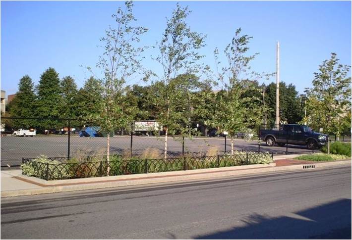
Tree trenches are a system of trees that are connected by an underground infiltration structure. The system consists of a stormwater tree trench or box lined with geotextile fabric with structural stone, gravel or soil boxes in which the trees are placed. Tree systems consist of an engineered soil or rock layer designed to treat stormwater runoff via filtration through plant and soil/rock media, and through evapotranspiration from trees. Discharge of this stored runoff occurs through infiltration into the surrounding naturally permeable soil. Tree species are carefully selected to survive both inundation and drought conditions in urban environments where they will be potentially affected by chloride and other traffic concerns. Tree trenches and boxes drainage areas should be less than five acres depending on the size of each trench. Irrigation, whether manual or automated, is strongly encouraged during the tree’s establishment period.
For more information, see the following pages in this Manual.
Trees - general
- Overview for trees
- Types of tree BMPs
- Plant lists for trees
- Street sweeping for trees
- References for trees
- Supporting material for trees
Tree boxes/tree trenches
- Design guidelines for tree quality and planting - tree trenches and tree boxes
- Design guidelines for soil characteristics - tree trenches and tree boxes
- Construction guidelines for tree trenches and tree boxes
- Protection of existing trees on construction sites
- Operation and maintenance of tree trenches and tree boxes
- Assessing the performance of tree trenches and tree boxes
- Calculating credits for tree trenches and tree boxes
- Case studies for tree trenches and tree boxes
- Soil amendments to enhance phosphorus sorption
- Fact sheet for tree trenches and tree boxes
- Requirements, recommendations and information for using trees as a BMP in the MIDS calculator
| Applications | Treatment capabilities2, 3 | ||
|---|---|---|---|
| Residential | Yes | TSS | High4 |
| Commercial | Yes | TN | Low/Medium |
| Ultra-urban | Yes | TP | Medium/High5 |
| Industrial | Yes1 | Chloride | Low |
| Highway/road | No | Metals | High |
| Recreational | Yes | Oils and grease | High |
| Pathogens | High | ||
| 1Unless the infiltration practice is located in an industrial area with exposed significant materials or from vehicle fuelling and maintenance areas. Infiltration BMPs are PROHIBITED in these areas; 2This is only for the portion of flow that enters the infiltration basin; by-passed runoff does not receive treatment; 3Low = < 30%; Medium = 30-65%; High = 65 -100%); 4Assumes adequate pre-treatment; 5Certain soil mixes can leach P. Source: see [1] | |||
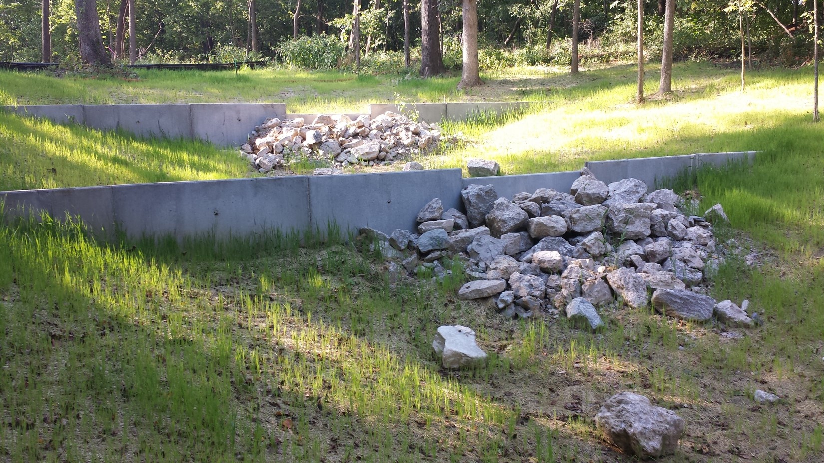
Dry swale with check dams
Similar to vegetated swales designed for stormwater conveyance, dry swales with check dams are designed as linear, multi-celled stormwater infiltration BMP’s. By incorporating earthen or structural check dams, runoff is retained and infiltrated along a series of narrow, shallow basins or cells. Coarse vegetation such as decorative plantings or even turf grass slow runoff movement. This system is designed to move, store, and infiltrate runoff from impervious surfaces such as linear roadways or parking lots. Dry swales are best designed for sites under one acre in size.
For more information see the following sections in the Minnesota Stormwater Manual.
- Terminology for swales (grass channels)
- Overview for dry swale (grass swale)
- Design criteria for dry swale (grass swale)
- Construction specifications for dry swale (grass swale)
- Operation and maintenance of dry swale (grass swale)
- Assessing the performance of dry swale (grass swale)
- Calculating credits for dry swale (grass swale)
- Cost considerations for dry swale (grass swale)
- Case studies for dry swale (grass swale)
- Plants for swales
- Check dams for stormwater swales
- External resources for dry swale (grass swale)
- References for dry swale (grass swale)
- Requirements, recommendations and information for using dry swale (grass swale) without an underdrain in the MIDS calculator
- Requirements, recommendations and information for using dry swale (grass swale) with an underdrain in the MIDS calculator
- Requirements, recommendations and information for using swale side slope as a BMP in the MIDS calculator
| Applications | Treatment capabilities2, 3 | ||
|---|---|---|---|
| Residential | Yes | TSS | High4 |
| Commercial | Yes | TN | Low/Medium |
| Ultra-urban | Limited6 | TP | Low/Medium5 |
| Industrial | Yes1 | Chloride | Low |
| Highway/road | Yes | Metals | High |
| Recreational | Yes | Oils and grease | High |
| Pathogens | Medium | ||
| 1Unless the infiltration practice is located in an industrial area with exposed significant materials or from vehicle fuelling and maintenance areas. Infiltration BMPs are PROHIBITED in these areas; 2This is only for the portion of flow that enters the infiltration basin; by-passed runoff does not receive treatment; 3Low = < 30%; Medium = 30-65%; High = 65 -100%); 4Assumes adequate pre-treatment; 5Certain soil mixes can leach P; 6Due to a size restriction. Source: see [2] | |||
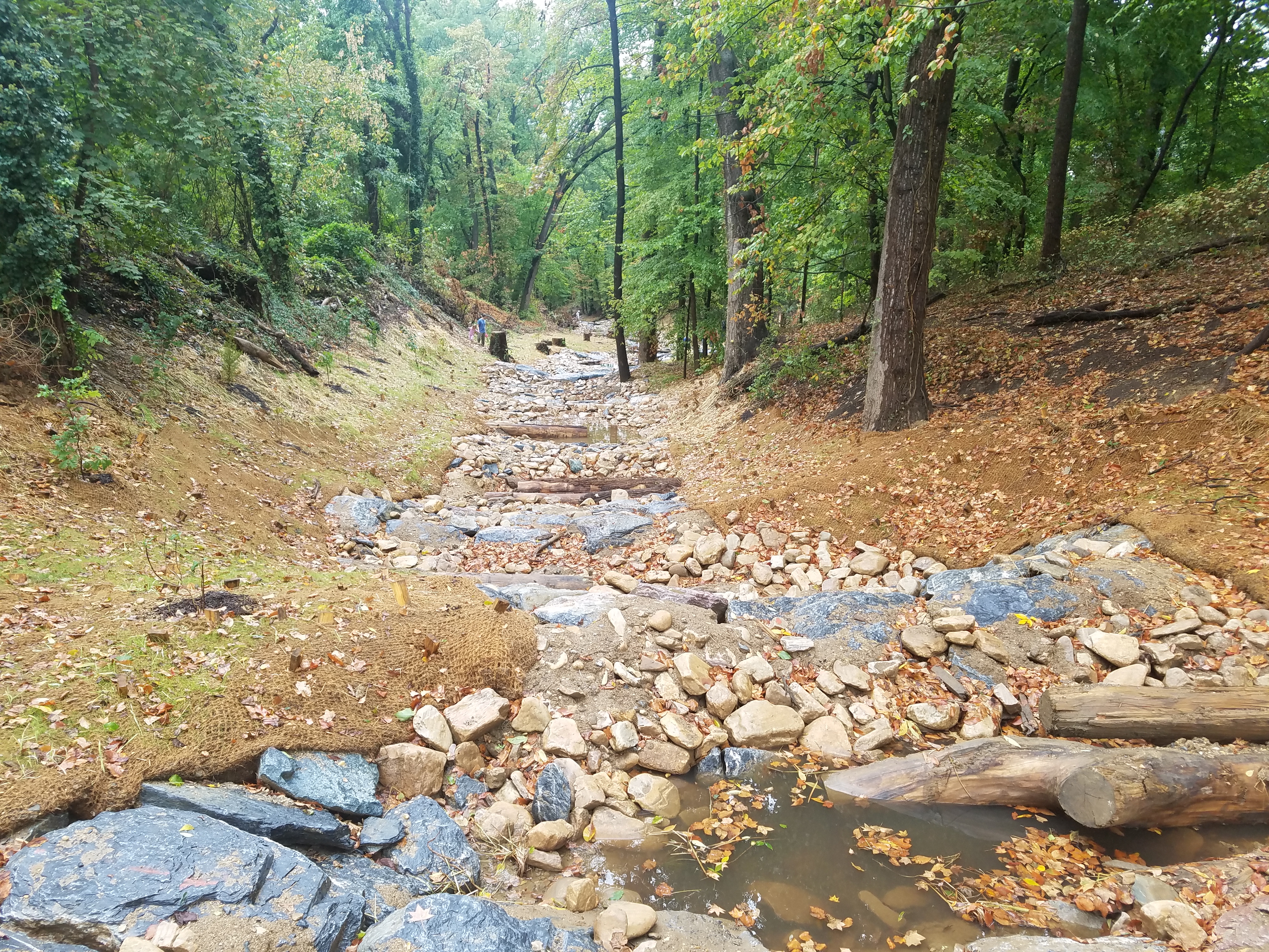
High gradient stormwater step-pool swale with check dams

Stormwater step pools are defined by its design features that address higher energy flows due to more dramatic slopes than dry or wet swales. Using a series of pools, riffle grade control, native vegetation and a sand seepage filter bed, flow velocities are reduced, treated, and, where applicable, infiltrated. to shallow groundwater. The physical characteristics of the stormwater step pools are similar to Rosgen A or B stream classification types, where “bedform occurs as a step/pool, cascading channel which often stores large amounts of sediment in the pools associated with debris dams” (Rosgen, 1996). These structures feature surface/subsurface runoff storage seams and an energy dissipation design that is aimed at attenuating the flow to a desired level through energy and hydraulic power equivalency principles (Anne Arundel County, 2009). Stormwater step pools are designed with a wide variety of native plant species depending on the hydraulic conditions and expected post-flow soil moisture at any given point within the stormwater step pool.
For more information see the following sections in the Minnesota Stormwater Manual.
- Terminology for high-gradient stormwater step-pool swale
- Overview for high-gradient stormwater step-pool swale
- Design criteria for high-gradient stormwater step-pool swale
- Construction specifications for high-gradient stormwater step-pool swale
- Operation and maintenance of high-gradient stormwater step-pool swale
- Assessing the performance of high-gradient stormwater step-pool swale
- Check dams for stormwater swales
- Plants for swales
- Calculating credits for high-gradient stormwater step-pool swale
- Cost considerations
- External resources for high-gradient stormwater step-pool swale
- References for high-gradient stormwater step-pool swale
| Applications | Treatment capabilities3, 4 | ||
|---|---|---|---|
| Residential | Yes | TSS | Medium5 |
| Commercial | Yes | TN | Low |
| Ultra-urban | Limited1 | TP | Medium6 |
| Industrial | Yes2 | Chloride | Low |
| Highway/road | Yes | Metals | Medium |
| Recreational | Yes | Oils and grease | Low |
| Pathogens | Low | ||
| 1Due to size restriction; 2Unless the infiltration practice is located in an industrial area with exposed significant materials or from vehicle fuelling and maintenance areas. Infiltration BMPs are PROHIBITED in these areas; 3This is only for the portion of flow that enters the infiltration basin; by-passed runoff does not receive treatment; 4Low = < 30%; Medium = 30-65%; High = 65 -100%); 5Assumes adequate pre-treatment; 6Certain soil mixes can leach P. Source: see [3] | |||
Non-structural infiltration practices
The practices briefly described in this section are not considered infiltration structures because they do not capture a design volume of water and infiltrate that water at the point of capture. These practices can result in significant volumes of water being infiltrated, however.
Harvest and use/reuse systems
A stormwater harvest and reuse system is a constructed system that captures and retains stormwater for beneficial use at a different time or place than when or where the stormwater was generated. The most common use of retained water is irrigation, but captured water may be used for other purposes, such as indoor toilet flushing. The volume of water potentially infiltrated is a function of the storage capacity of the system. Volumes are restricted to relatively small amounts when tanks are used for storage. Tank storage is commonly used in more urban areas where surface space is restricted. If constructed ponds or wetlands are used for storage, significant volumes of water can be infiltrated through irrigation.
For more information, see the following sections.
- Stormwater and rainwater harvest and use/reuse
- Design considerations for constructed stormwater ponds used for harvest and irrigation use/reuse
Vegetated filter strips
Vegetated filter strips are vegetated areas where stormwater runoff can be directed. As water flows over the filter strip, some infiltration can occur. Infiltration is enhanced by the following conditions.
- Coarse-textured soils
- Native perennial vegetation
- Increased surface roughness
- Decreased land slope
- Spreading the runoff over a larger area
For more information see Overview for pretreatment vegetated filter strips and Design, construction, operation and maintenance specifications for pretreatment vegetated filter strips.

Enhanced turf
Infiltration can be enhanced on soils that have been improved or amended. This manual contains limited information on enhanced turf and does not provide guidance for design, construction, maintenance, and assessment of enhanced turf. Information on use of compost in soil and credits associated with improved turf can be found on the Turf page. A discussion of alleviating compaction from construction activities can be found here.
Warning: Enhanced turf cannot be used to meet requirements of the Construction Stormwater General permit because infiltrated water does not represent an instantaneous volume.
Swales with no check dams
Similar to vegetated filter strips, water can infiltrate into soils underlying swales. The amount of infiltration is typically very low, but can be enhanced by employing the same practices that enhance infiltration in vegetated filter strips.
Unit processes for different infiltration BMPs
The following table provides a summary of unit processes for the different infiltration BMPs.
Information tables
The following tables describe and differentiate different characteristics of stormwater infiltration BMPs.
Overview table
The following table provides a brief description and schematic of each stormwater infiltration BMP.
| Stormwater BMP | General Overview | Illustration |
|---|---|---|
| Infiltration Basin | A natural or constructed impoundment that captures, temporarily stores and infiltrates the design volume of water into the surrounding naturally permeable soil over several days. In the case of a constructed basin, the impoundment is created by excavation or embankment. | |
| Bioinfiltration Basin | Often called rain gardens, bioinfiltration basins use engineered or mixed soils and plantings to capture and infiltrate runoff. Pollutants are removed using highly permeable soils that are able to draw the basin down in less than 48 hours. | |
| Infiltration Trench Synonym: Infiltration Gallery | A shallow excavated trench that is backfilled with a coarse stone aggregate allowing for the temporary storage of runoff in the void space of the material. Discharge of this stored runoff occurs through infiltration into the surrounding naturally permeable soil. |
|
| Dry Well Synonym: Infiltration Tube, French Drain, Soak‐Away Pits, Soak Holes | A smaller variation of an infiltration trench. It is a subsurface storage facility (a structural chamber or an excavated pit backfilled with a coarse stone aggregate) that receives and temporarily stores stormwater runoff. Discharge of this stored runoff occurs through infiltration into the surrounding naturally permeable soil. Due to their size, dry wells are typically designed to handle stormwater runoff from smaller drainage areas. | |
| Underground Infiltration | Several underground infiltration systems, including pre‐manufactured pipes, vaults, and modular structures, have been developed as alternatives to infiltration basins and trenches for space‐limited sites and stormwater retrofit applications. These systems are similar to infiltration basins and trenches in that they are designed to capture, temporarily store and infiltrate the design volume of stormwater over several days. Discharge of this stored runoff occurs through infiltration into the surrounding naturally permeable soil. | |
| Dry Swale with Check Dams | Similar to vegetated swales designed for stormwater conveyance, dry swales with check dams are designed as linear, multi‐celled stormwater infiltration BMPs. By incorporating earthen, structural or rock check dams, runoff is retained and infiltrated along a series of narrow, shallow basins or cells. Coarse vegetation such as decorative plantings or even turf grass slow runoff movement. This system is designed to move, store, and infiltrate runoff from impervious surfaces such as linear roadways or parking lots. | |
| Permeable Pavement | Permeable pavements are paving surfaces that allow stormwater runoff to filter through surface voids into an underlying stone reservoir for infiltration and/or storage. The most commonly used permeable pavement surfaces are pervious concrete, porous asphalt, and permeable interlocking concrete pavers (PICP). All permeable pavements have a similar structure, consisting of a surface pavement layer, an underlying stone aggregate reservoir layer, optional underdrains and geotextile over uncompacted soil subgrade. Discharge of this stored runoff occurs through infiltration into the surrounding naturally permeable soil. | |
| Tree Trench/Tree Box | A system of trees that are connected by an underground infiltration structure. The system consists of a trench lined with geotextile fabric with structural stone, gravel or soil boxes in which the trees are placed. Tree systems consist of an engineered soil layer designed to treat stormwater runoff via filtration through plant and soil media, and through evapotranspiration from trees. Discharge of this stored runoff occurs through infiltration into the surrounding naturally permeable soil. |
Contributing drainage area table
The following table provides a summary of recommended contributing drainage area for each stormwater infiltration BMP.
Contributing drainage area is defined as the total area, including pervious and impervious surfaces, contributing to a best management practice (BMP). It is assumed that in most cases, with the exception of green roofs and many permeable pavement systems, impervious surfaces will constitute more than 50 percent of the contributing area to the BMP and that most of this impervious is directly connected impervious. The recommended contributing area to a BMP may be modified for the following conditions.
- The recommended contributing area may be increased if pervious surfaces constitute the majority of the contributing area and soils are hydrologic soil group (HSG) A or B
- The recommended contributing area should be decreased if impervious surfaces contribute more than 80 percent of the contributing area or if the entire impervious surface is directly connected and routed to the BMP
- The recommended contributing area should be decreased or may be increased based on pollutant loading (decrease with higher pollutant loads)
Runoff coefficients may be calculated for an area contributing to a BMP. Runoff coefficients greater than about 0.55 are typical of urban areas having 50 percent or more impervious surface. Typical runoff coefficients are shown on these pages ([4], [5]) and discussed here. To see how runoff curve number is associated with impervious percentages, see at this link.
Treatment properties table
The following table provides information on pollutant removal mechanism(s), location in the stormwater treatment train, general pollutant removal, and potential applications for each of the stormwater BMPs.
| Stormwater BMP | Illustration | Pollutant Removal Mechanism | Location in Treatment Train | Pollutant Removal 1,2 | Potential Application 1 |
|---|---|---|---|---|---|
| Infiltration Basin | Sedimentation / Infiltration | End |
TSS: High TN: Medium/High TP: Medium/High Chloride: Low Metals: High Oils and Grease: High Pathogens: High |
Residential: Yes Commercial: Yes Ultra Urban: Limited Industrial: Limited Retrofit: Yes Highway/Road: Limited |
|
| Bioinfiltration Basin | Sedimentation / Infiltration | Beginning |
TSS: High TN: Low/Medium TP: Medium/High Chloride: Low Metals: High Oils and Grease: High |
Residential: Yes Commercial: Yes Ultra Urban: Limited Industrial: Limited Retrofit: Yes Highway/Road: Limited |
|
| Infiltration Trench Synonym: Infiltration Gallery |
Infiltration | nd |
TSS: High TN: Medium/High TP: Medium/High Chloride: Low Metals: High Oils and Grease: High Pathogens: High |
Residential: Yes Commercial: Yes Ultra Urban: Yes Industrial: Limited Retrofit: Yes Highway/Road: Yes |
|
| Dry Well Synonym: Infiltration Tube, French Drain, Soak‐Away Pits, Soak Holes |
Infiltration | throughout |
TSS: High TN: Medium/High TP: Medium/High Chloride: Low Metals: High Oils and Grease: High Pathogens: High |
Residential: Yes Commercial: Yes Ultra Urban: Yes Industrial: Limited Retrofit: Yes Highway/Road: No |
|
| Underground Infiltration | Sedimentation / Infiltration / Flotation/Skimming | End |
TSS: High TN: Medium/High TP: Medium/High Chloride: Low Metals: High Oils and Grease: High Pathogens: High |
Residential: Yes Commercial: Yes Ultra Urban: Yes Industrial: Limited Retrofit: Yes Highway/Road: Limited |
|
| Dry Swale with Check Dams | Sedimentation / Infiltration | Throughout |
TSS: High TN: Low/Medium TP: Low/Medium Chloride: Low Metals: High Oils and Grease: High Pathogens: Medium |
Residential: Yes Commercial: Yes Ultra Urban: Limited Industrial: Yes Retrofit: Limited Highway/Road: Yes |
|
| Permeable Pavement | Infiltration | Beginning |
TSS: High TN: Medium/High TP: Medium/High Chloride: Low Metals: High Oils and Grease: High |
Residential: Yes Commercial: Yes Ultra Urban: Yes Industrial: Limited Retrofit: Yes Highway/Road: Limited |
|
| Tree Trench/Tree Box | Infiltration, Transpiration | Throughout |
TSS: High TN: Medium/High TP: Medium/High Chloride: Low Metals: High Oils and Grease: High Pathogens: High |
Residential: Limited Commercial: Yes Ultra Urban: Yes Industrial: Limited Retrofit: Yes Highway/Road: Limited |
|
| 1 Treatment Capabilities and Potential Applications referenced from Manual Section BMP's for stormwater infiltration 2 Low = < 30%; Medium = 30‐65%; High = 65‐100% |
|||||
Selection considerations table
The following table provides information on general cost, maintenance requirements, pretreatment needs, and habitat quality for each of the stormwater infiltration BMPs.
| Stormwater BMP | Illustration | Cost | Maintenance Requirements 3 | Pre‐treatment 4 | Habitat Quality 5 |
|---|---|---|---|---|---|
| Infiltration Basin | Low $0.5‐$1.3 CF | Simple‐Intensive | Needed Oil/Water Separator, Vegetated Filter, Sediment Basin, Water Quality Inlets | Low | |
| Bioinfiltration Basin | Low $0.5‐$1.3 CF | Simple‐Intensive | Needed Oil/Water Separator, Vegetated Filter, Sediment Basin, Water Quality Inlets | Medium‐High | |
| Infiltration Trench Synonym: Infiltration Gallery | Low $1‐$4 CF | Medium | Needed Oil/Water Separator, Vegetated Filter, Sediment Basin, Water Quality Inlets | None | |
| Dry Well Synonym: Infiltration Tube, French Drain, Soak‐Away Pits, Soak Holes | Low $1‐$4 CF | Medium | Needed Oil/Water Separator, Vegetated Filter, Water Quality Inlets | None | |
| Underground Infiltration | High 14 CF | Medium | Needed Oil/Water Separator, Water Quality Inlets | None | |
| Dry Swale with Check Dams | Low $.5‐$1.3 CF | Simple‐Medium | Needed Vegetated Filter, Water Quality Inlets | Low‐Medium | |
| Permeable Pavement | Medium 3‐10 CF | Medium | No Pretreatment Required | None | |
| Tree Trench/Tree Box |
High $1.80 ‐ $12.70 CF based on recommended soil volume of 1,414 CF per tree |
Intensive | Needed Oil/Water Separator, Water Quality Inlets | Medium | |
| 1 Maintenance requirements to be addressed and updated in future section 2 Pretreatment requirements to be revised as per updated section 3 Habitat quality refers to the possible diversity of plantings commonly installed with each BMP |
|||||
See Infiltration Summary Table
To see all information contained in the previous tables in a single table, click on the following link: Infiltration Summary Table
Related pages for stormwater infiltration
- Overview of stormwater infiltration
- Pre-treatment considerations for stormwater infiltration
- Pollutant fate and transport in stormwater infiltration systems
- Surface water and groundwater quality impacts from stormwater infiltration
- Stormwater infiltration and groundwater mounding
- Stormwater infiltration and setback (separation) distances
- Karst
- Shallow soils and shallow depth to bedrock
- Shallow groundwater
- Soils with low infiltration capacity
- Potential stormwater hotspots
- Stormwater and wellhead protection
- Stormwater infiltration and contaminated soils and groundwater
- Decision tools for stormwater infiltration
- References for stormwater infiltration
Related pages for infiltration BMPs
- Infiltration portal
- Overview for infiltration
- Design criteria for infiltration
- Construction specifications for infiltration
- Operation and maintenance of stormwater infiltration practices
- Assessing the performance of infiltration
- Calculating credits for infiltration
- Cost-benefit considerations for infiltration
- Case studies for infiltration
- External resources for infiltration
- References for infiltration
- Requirements, recommendations and information for using infiltration basin/underground infiltration BMPs in the MIDS calculator
- Understanding and interpreting soils and soil boring reports for infiltration BMPs
- Determining soil infiltration rates
- Cold climate considerations for infiltration practices - See [6], [7]